Optical imaging device and its light collector

An optical imaging and condenser technology, applied in optics, condensers, optical components, etc., can solve the problems of different imaging, asynchrony, non-uniform signal data processing, etc., to improve the service life and reduce the effect of interfering with imaging

Active Publication Date: 2018-10-30
NINGBO SUNNY OPOTECH CO LTD
View PDF5 Cites 0 Cited by
  • Summary
  • Abstract
  • Description
  • Claims
  • Application Information

AI Technical Summary

Problems solved by technology

But the existing optical imaging equipment has the following problems: first, the imaging of the existing optical imaging equipment is limited by the imaging angle (or viewing angle) or the imaging direction, and it can only make the image in a certain direction or the effective viewing angle range The subject (or imaging object) is imaged, while the objects on both sides of the optical imaging device and on the back of the device cannot be imaged and displayed
When multiple cameras or sensors are used to achieve large-angle imaging, and different cameras or sensors are imaged separately, the inhomogeneity (or the sameness) of other different functional components corresponding to these cameras or sensors and the asynchronous processing of signal data Both will lead to different imaging, which will also affect the imaging quality of the optical imaging device

Method used


Image

  • Optical imaging device and its light collector
  • Optical imaging device and its light collector
  • Optical imaging device and its light collector

Examples


Embodiment Construction

[0058] The following description serves to disclose the present invention to enable those skilled in the art to carry out the present invention. The preferred embodiments described below are only examples, and those skilled in the art can devise other obvious variations. The basic principles of the present invention defined in the following description can be applied to other embodiments, variations, improvements, equivalents and other technical solutions without departing from the spirit and scope of the present invention.

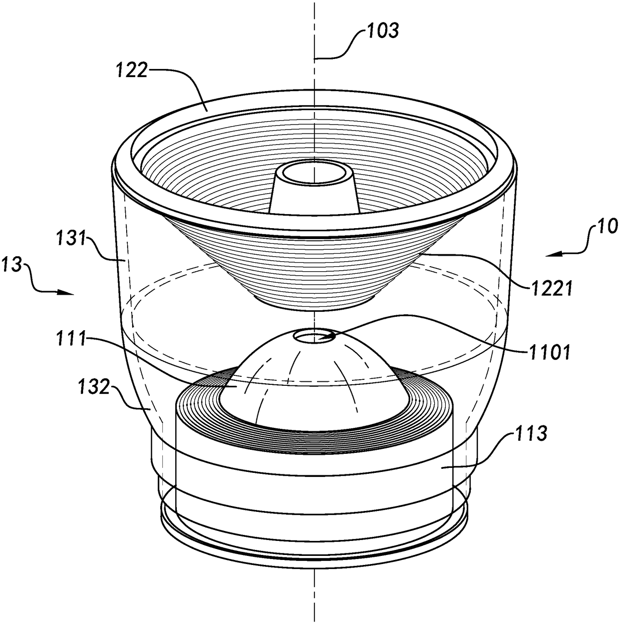
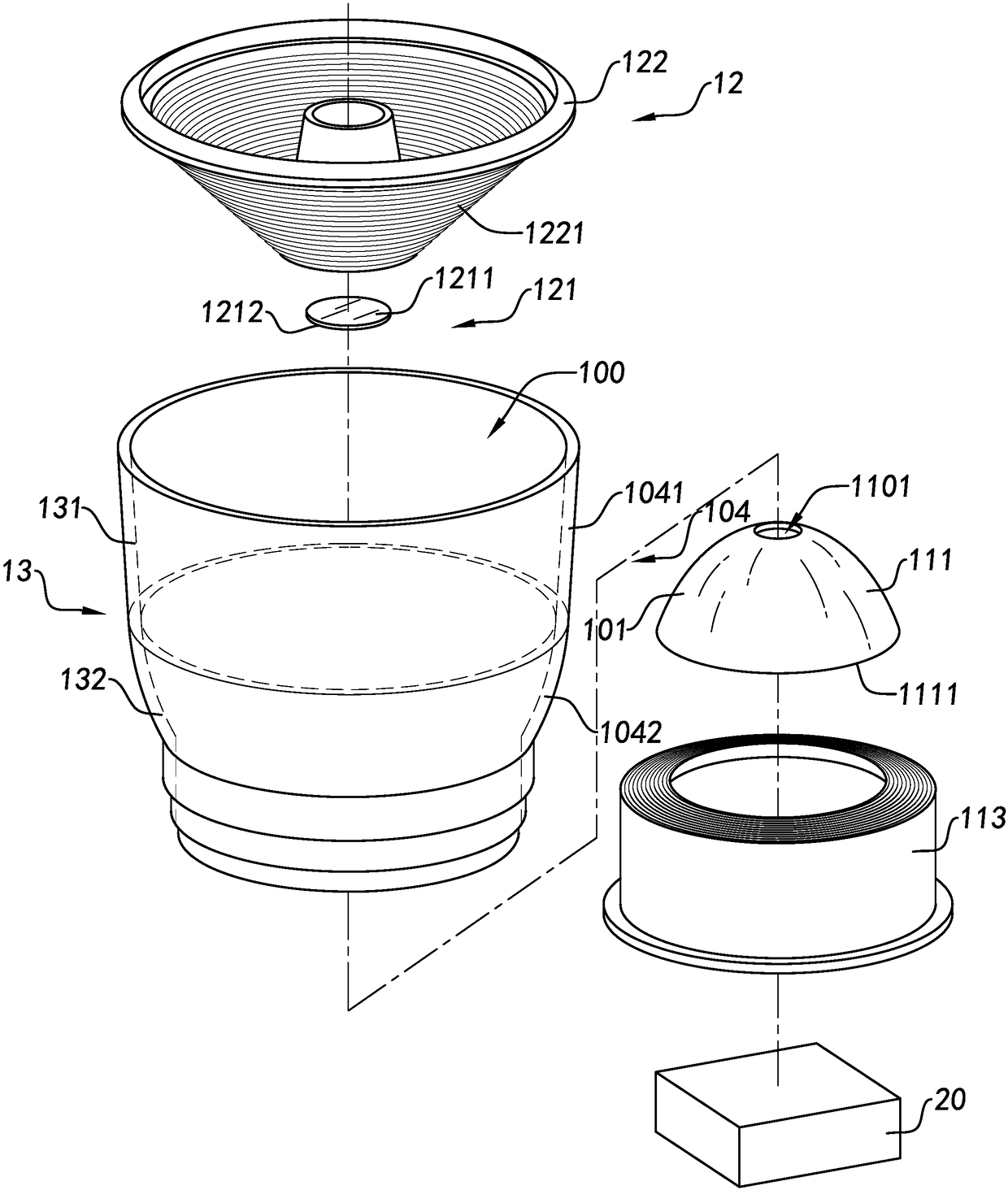
[0059] With reference to the accompanying drawings of the present invention Figure 1 to Figure 7B , an optical imaging device according to a preferred embodiment of the present invention is illustrated, wherein the optical imaging device includes a concentrator 10, an optical sensor 20 and a signal processing module 30, wherein the concentrator 10 is configured to converge the concentrator The reflected light of the imaged object within the large-angle ...


PUM


Abstract

The invention provides an optical imaging device. The device comprises a condenser, an optical sensor and a signal processing module. The condenser forms one condensed light path. The condenser is set to be capable of gathering reflected light of an imaging object to the condensed light path. The optical sensor is set in the condensed light path. The optical sensor is used for inducing the reflected light gathered to the condensed light path and generating a corresponding photo-induction signal. The signal processing module is electrically connected to the optical sensor and is set to be capable of receiving the photo-induction signal generated by the optical sensor.

Description

technical field [0001] The present invention relates to optical imaging equipment, in particular to a light concentrator for optical imaging, wherein the light concentrator can gather the reflected light of an imaging object in a large angle range, so that the reflected light of an imaging object in a large angle range sensed by a single sensor. Background technique [0002] With the development of science and technology, optical imaging devices (devices) have been successively developed, such as cameras, video cameras, etc., have been successively developed and continuously improved. But the existing optical imaging equipment has the following problems: first, the imaging of the existing optical imaging equipment is limited by the imaging angle (or viewing angle) or the imaging direction, and it can only make the image in a certain direction or the effective viewing angle range The subject (or imaged object) is imaged, but the objects on both sides of the optical imaging d...

Claims


Application Information

Patent Timeline
Patent Type & Authority Patents(China)
IPC IPC(8): G02B19/00
CPCG02B19/0028G02B19/0076
Inventor 胡银辉章斌张泽霖
Owner NINGBO SUNNY OPOTECH CO LTD
Why Eureka
Try Eureka