
Scanning camera and application thereof

An imaging and optical imaging technology, applied in the field of surround-view cameras, can solve the problems of viewer discomfort, unnatural imaging pictures, and difficulty, and achieve the effect of reducing interference imaging and improving light reflection efficiency.

Inactive Publication Date: 2017-11-07
NINGBO SUNNY OPOTECH CO LTD
View PDF3 Cites 2 Cited by
  • Summary
  • Abstract
  • Description
  • Claims
  • Application Information

AI Technical Summary

Problems solved by technology

In addition, the splicing of two images requires that the two images be cut at appropriate positions, but it is very difficult to determine the splicing positions of the two images at the same time
And once the splicing between the two images fails to achieve a proper match, it will lead to an unnatural image in the final image
In severe cases, it may cause discomfort to the viewer

Method used


Image

  • Scanning camera and application thereof
  • Scanning camera and application thereof
  • Scanning camera and application thereof

Examples


Embodiment Construction

[0049] The following description serves to disclose the present invention to enable those skilled in the art to carry out the present invention. The preferred embodiments described below are only examples, and those skilled in the art can devise other obvious variations. The basic principles of the present invention defined in the following description can be applied to other embodiments, variations, improvements, equivalents and other technical solutions without departing from the spirit and scope of the present invention.

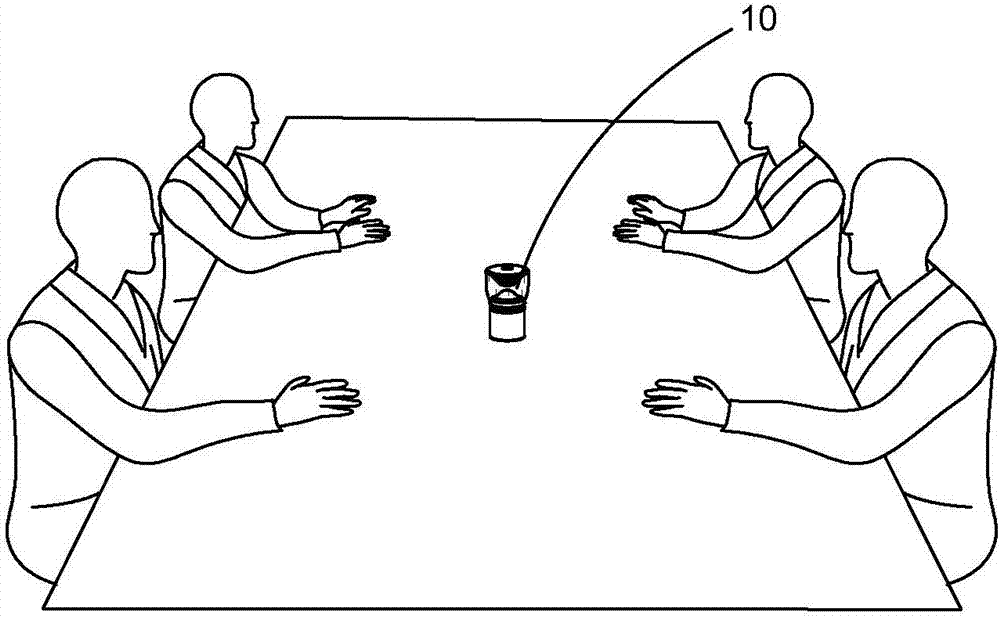
[0050] figure 1 What is shown is that the optical imaging device of the present invention is applied in a teleconferencing system. People participating in the conference can sit around the surround-view camera device, and the surround-view camera device can simultaneously and equally take pictures of the conference environment, such as the people participating in the conference and the conference room where the conference is held. When the surround-view...


PUM


Abstract

The invention provides an optical imaging device comprising a condenser, wherein the condenser is provided with an incident surface and an axle wire and forms a condensation optical path, the incident surface is set to continuously extend around the axle wire, so that the condenser has a scanning imaging visual angle and can collect the reflected light of imaging objects on all imaging angles to the condensation optical path; an optical sensor, wherein the optical sensor is arranged on the condensation optical path, and the optical sensor is set to synchronously and identically sense the reflected light of the imaging objects on all imaging angles that is collected to the condensation optical path and generate a corresponding optical sensing signals; and a signal processing module, wherein the signal processing module comprises a signal processing module, the signal processing module is electrically connected with the optical sensor, and the signal processing module is set to receive the optical sensing signals generated by the optical sensor.

Description

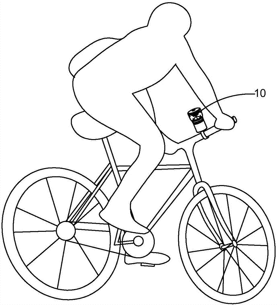
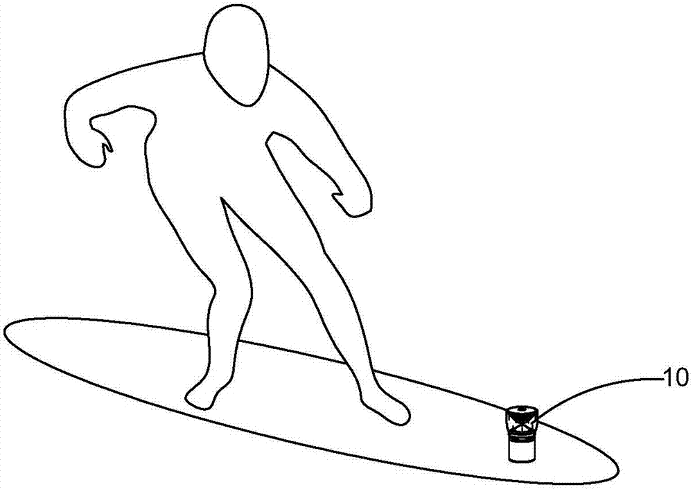
technical field [0001] The invention relates to an optical imaging device, in particular to a surround-view camera for optical imaging and an application thereof. Background technique [0002] Large-angle range, even 360-degree range camera (surround-view optical camera), is widely used in many fields, such as teleconferencing systems, monitoring, aerial photography, diving photography and landscape photography. The teleconferencing system needs to look around the camera so that the images of everyone at the meeting site appear in the virtual meeting place, so as to facilitate the holding of the meeting and improve the meeting experience of everyone participating in the meeting. During aerial photography, it is generally necessary to take all-round shots of the shooting target or shooting area in order to obtain a satisfactory image. Surveillance systems are sometimes more demanding. In order to be able to realize the purpose of monitoring, the monitoring system often need...

Claims


Application Information

Patent Timeline
IPC IPC(8): H04N5/225H04N5/232G02B19/00
CPCG02B19/00H04N23/55H04N23/54H04N23/698H04N23/69
Inventor 顾亦武章斌胡银辉毛鲲
Owner NINGBO SUNNY OPOTECH CO LTD
Learn More