Manufacturing technique and device for improved bainite nodular cast iron composite roller provided with forged steel roller neck

A technology of bainitic nodular ink and composite roll, which is applied in the field of metal pressure processing, can solve the problems of rapid decrease in hardness and wear resistance, poor thermal fatigue resistance, low thermal fatigue resistance, etc., and achieve good red hardness and high temperature resistance. Abrasiveness, good mechanical properties, and excellent crystal structure

Active Publication Date: 2016-03-30
丹阳恒庆复合材料科技有限公司
View PDF4 Cites 13 Cited by
  • Summary
  • Abstract
  • Description
  • Claims
  • Application Information

AI Technical Summary

Problems solved by technology

Therefore, when the core material is cast steel, a good composite interface cannot be obtained.
[0012] 3) Composite rolls with forged steel cores with high strength and high toughness cannot be produced
At present, it is mainly manufactured by the centrifugal composite casting process in China. Due to the limitation of the manufacturing process, the core is made of nodular cast iron. Due to the low strength of nodular cast iron, it is easy to break the roll during steel rolling production, which seriously affects the steel rolling production and product quality.
[0023] At present, centrifugal bainite rolls are usually used in the rolling of finished bars, slitting racks, and strips. This roll has the following shortcomings in the long-term use process: 1. The hardness drop is large, and the centrifugal bainite rolls From one use to the last use, the material structure changes greatly, the hardness and wear resistance decrease rapidly, and the rolling tonnage can decrease by 50-70 tons; 2. The thermal fatigue resistance is poor, and the rolls work at high temperature for a long time. Due to the thermal fatigue resistance of the roll, after a period of use, the roll is prone to cracks and surface blocks, which seriously affects the quality of the rolled pie

Method used


Image

  • Manufacturing technique and device for improved bainite nodular cast iron composite roller provided with forged steel roller neck
  • Manufacturing technique and device for improved bainite nodular cast iron composite roller provided with forged steel roller neck
  • Manufacturing technique and device for improved bainite nodular cast iron composite roller provided with forged steel roller neck

Examples


Embodiment 1

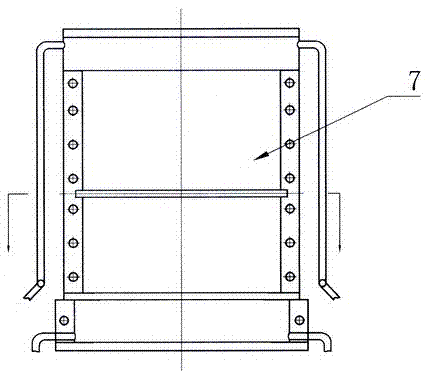
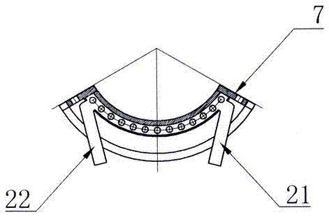
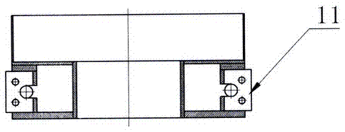
[0067] Example 1: In figure 1 , figure 2 , image 3 , Figure 4 , Figure 5 , Image 6 In the equipment, the equipment has a gantry-type regional directional solidification lifting device 16, a lifting platform 17 is installed on the gantry-type regional directional solidification lifting device 6, and an electromagnetic induction heater 8 is installed on the lifting platform 17, which is rotated and lifted by a lifting motor 14. The screw 15 or hydraulic equipment drives the lifting platform 17 to move up and down at a set speed. An electromagnetic induction power supply control cabinet 19 is installed on the side of the gantry-type area directional solidification lifting equipment 16, and the two output ends of the electromagnetic induction power control cabinet 19 are cooled by water The cable 20 is connected to the two ends of the electromagnetic induction heater 8. There is a base support at the lower part of the gantry type area directional solidification lifting equipmen...

Embodiment 2

[0087] Example 2: In figure 1 , figure 2 , image 3 , Figure 4 , Figure 5 , Image 6 In the equipment, the equipment has a gantry-type regional directional solidification lifting device 16, a lifting platform 17 is installed on the gantry-type regional directional solidification lifting device 6, and an electromagnetic induction heater 8 is installed on the lifting platform 17, which is rotated and lifted by a lifting motor 14. The screw 15 or hydraulic equipment drives the lifting platform 17 to move up and down at a set speed. An electromagnetic induction power supply control cabinet 19 is installed on the side of the gantry-type area directional solidification lifting equipment 16, and the two output ends of the electromagnetic induction power control cabinet 19 are cooled by water The cable 20 is connected to the two ends of the electromagnetic induction heater 8. There is a base support at the lower part of the gantry type area directional solidification lifting equipmen...

Embodiment 3

[0106] Example 3: In figure 1 , figure 2 , image 3 , Figure 4 , Figure 5 In the equipment, the equipment has a gantry-type regional directional solidification lifting device 16, a lifting platform 17 is installed on the gantry-type regional directional solidification lifting device 6, and an electromagnetic induction heater 8 is installed on the lifting platform 17, which is rotated and lifted by a lifting motor 14. The screw 15 or hydraulic equipment drives the lifting platform 17 to move up and down at a set speed. An electromagnetic induction power supply control cabinet 19 is installed on the side of the gantry-type area directional solidification lifting equipment 16, and the two output ends of the electromagnetic induction power control cabinet 19 are cooled by water The cable 20 is connected to the two ends of the electromagnetic induction heater 8. There is a base support at the lower part of the gantry type area directional solidification lifting equipment 16, a supp...


PUM


Abstract

The invention discloses a manufacturing technique and device for an improved bainite nodular cast iron composite roller provided with a forged steel roller neck. The improved bainite nodular cast iron composite roller provided with the forged steel roller neck is prepared from, by mass, 3.0%-3.6% of C, 0.60%-1.20% of Si, 0.30%-1.20% of Mn, 3.0%-5.0% of Ni, 1.0%-2.0% of Cr, 0.40%-1.2% f Mo, 0.1%-2% of W, 0.5%-1.0% of Cu, 0-0.05% of P, 0-0.30% of S, 0.04%-0.06% of Mg, 0.1%-0.3% of Nb, 0.1%-0.30% of Ti, 0.2%-0.6% of V, 0.05%-0.2% of B, 1.5%-2.5% of Ba, 1%-2% of Ca, 1%-3% of Sb, 0.02%-0.18% of N, 1.0%-2.0% of Y/RE, and the balance Fe and inevitable trace elements. According to the manufacturing technique and device for the improved bainite nodular cast iron composite roller provided with the forged steel roller neck, yttrium-based rare earth is used for nodularization, Ba, Ca and silicon iron are used for combined inoculation, Nb, Ti, V, B and Sb are added for modification treatment, and thus the mechanical property of the roller is improved; by the adoption of the forged steel roller neck, the strength of the roller is improved; integral in-mold heating and casting of a core rod are conducted through an induction heater, and a water-cooling crystallizer is used for formation; the interface of a composite layer can be controlled dynamically, the technique is simple, power consumption is low, the cost is low, composition segregation is avoided, and the service life of the roller is long.

Description

Technical field [0001] The invention belongs to the technical field of metal pressure processing, and in particular relates to a manufacturing process and equipment for an improved forged steel roll neck bainite ductile iron composite roll, which is suitable for the manufacture of composite rolls in the steel rolling industry. Background technique [0002] Rolls are known as the "mother of steel". They are tools for plastic deformation of metal materials in the rolling production of steel, aluminum, copper and other metals. It is an important large-scale component that determines the production efficiency of the rolling mill and the quality and economy of the rolled material. The consumption cost of rolling indispensable key components and the most important bulk consumable components is about 5% to 15% of the rolling production cost. If you consider factors such as production downtime, reduced production, and increased equipment maintenance due to roll consumption, the proportio...

Claims


Application Information

Patent Timeline
IPC IPC(8): B22D19/16C22C37/10C22C37/08
CPCB22D19/16C22C37/08C22C37/10
Inventor 丁家伟丁刚耿德英鹿微微鹿策施孟达孔军
Owner 丹阳恒庆复合材料科技有限公司
Why Eureka
Try Eureka