

Rotation driving device capable of being implemented in a relatively high temperature environment
A technology of temperature environment and rotation drive, applied in the direction of electromechanical devices, electrical components, synchronous machines, etc., can solve the problems of large drive torque, complex structure, large shaft radial size, etc., to increase the rotation output torque, simplify manufacturing and equipment , The effect of reducing the axial and radial dimensions
- Summary
- Abstract
- Description
- Claims
- Application Information
AI Technical Summary
Problems solved by technology
Method used
Image

Examples
no. 1 example
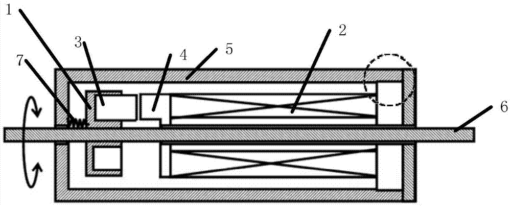
[0087] figure 1 It is a structural schematic diagram of the rotary driving device that can be implemented in a relatively high temperature environment in the first embodiment of the present invention. The first embodiment is a preferred example of the above-mentioned basic embodiment. In this embodiment, one side of the rotating shaft stator is provided with a rotating shaft mover; the number of the rotating shaft stator is one. The reset mechanism drives the opposite end surfaces of the mover magnet and the stator magnet to rotate to a dislocation position. The reset mechanism can be a hinge spring or a torsion spring. Such as figure 1 as shown, figure 1 The dotted line in the mark indicates the fixed position link of the rotating shaft stator, which can be fixed by interference fit or fastened connection by fasteners such as screws.
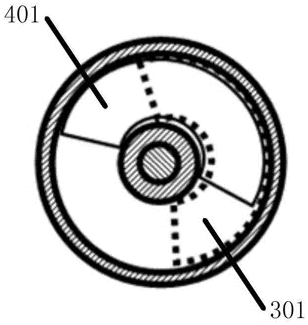
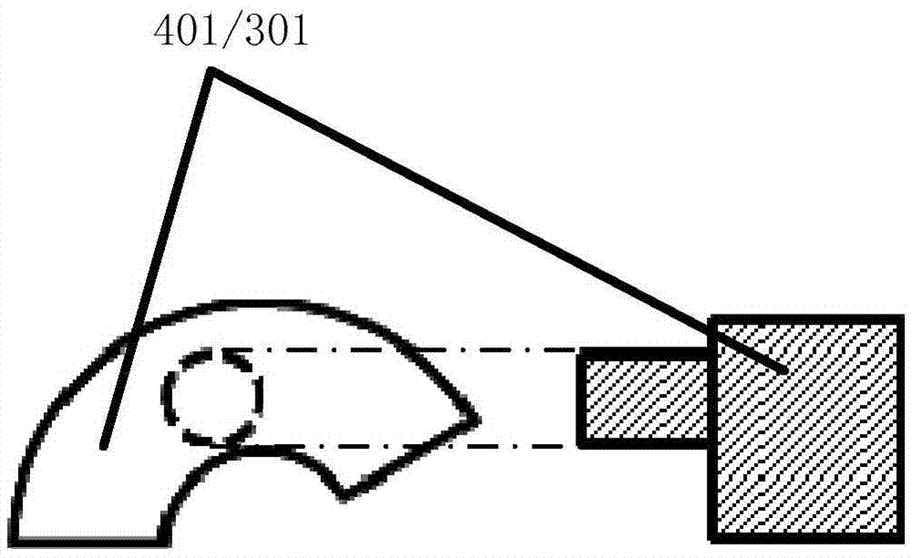
[0088] The shape of the opposite end faces of the mover magnet and the stator magnet can be adopted in various ways, such as Figure 2 t...
no. 2 example
[0091] Image 6 It is a schematic structural diagram of a rotary drive device capable of implementing a rotation drive in a relatively high temperature environment in the second embodiment of the present invention. The second embodiment is a preferred example of the above-mentioned basic embodiment. In this embodiment, both sides of the rotating shaft stator are provided with rotating shaft movers; both ends of the rotating shaft stator are respectively provided with stator magnets; and the stator magnets respectively located at both ends of the rotating shaft stator are coaxially arranged. The stator magnet set at one end of the stator of the rotating shaft is denoted as stator magnet A1, and the mover magnet which interacts with stator magnet A1 to form a magnetic circuit structure is denoted as mover magnet B1; the stator magnet set at the other end of the stator of the rotating shaft is denoted as stator magnet A2, the mover magnet that interacts with the stator magnet A2...
no. 3 example
[0094] Figure 7 It is a structural schematic diagram of a rotary drive device capable of implementing a rotation drive in a relatively high temperature environment in the third embodiment of the present invention. The third embodiment is a preferred example of the above-mentioned basic embodiment. In this embodiment, multiple rotating shaft stators are connected in series on the rotating shaft, and multiple sets of rotating shaft movers are correspondingly arranged, thereby increasing the output torque of the rotating shaft and providing greater driving force.
PUM
 Abstract
Description
Claims
Application Information