
An electromagnetic semi-active vibration isolator using asymmetric magnetic tooth structure to achieve quasi-zero stiffness characteristics

A quasi-zero stiffness, electromagnetic technology, applied in the direction of magnetic springs, springs/shock absorbers, springs, etc., can solve the problems that the vibration isolation system is difficult to achieve quasi-zero stiffness characteristics, difficult to adjust the static balance position, etc., to achieve zero stiffness Easier to obtain, compact and efficient effect

Active Publication Date: 2017-05-24
HARBIN ENG UNIV
View PDF2 Cites 7 Cited by
  • Summary
  • Abstract
  • Description
  • Claims
  • Application Information

AI Technical Summary

Problems solved by technology

However, the choice of series mode makes it more difficult to adjust the static equilibrium position of the entire vibration isolation system, which makes it difficult for the designed vibration isolation system to achieve quasi-zero stiffness characteristics

Method used


Image

  • An electromagnetic semi-active vibration isolator using asymmetric magnetic tooth structure to achieve quasi-zero stiffness characteristics
  • An electromagnetic semi-active vibration isolator using asymmetric magnetic tooth structure to achieve quasi-zero stiffness characteristics
  • An electromagnetic semi-active vibration isolator using asymmetric magnetic tooth structure to achieve quasi-zero stiffness characteristics

Examples


Embodiment Construction

[0019] The present invention is described in more detail below in conjunction with accompanying drawing example:

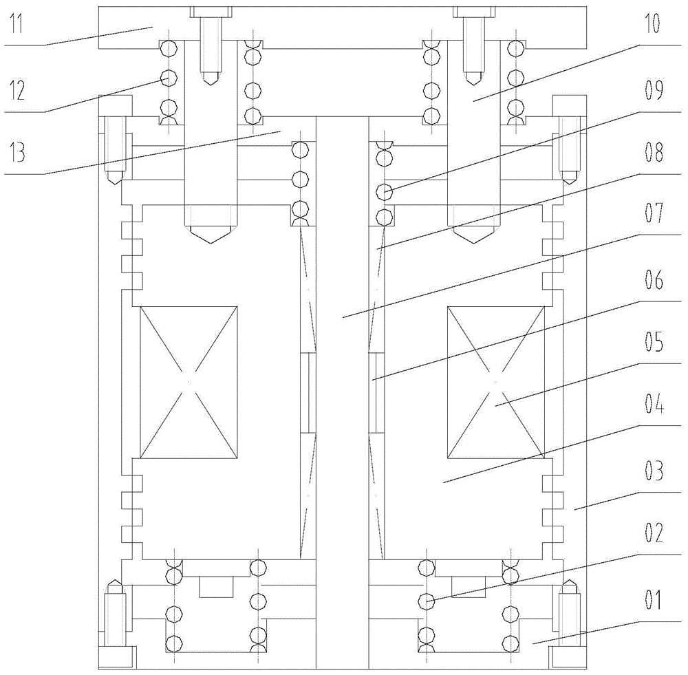
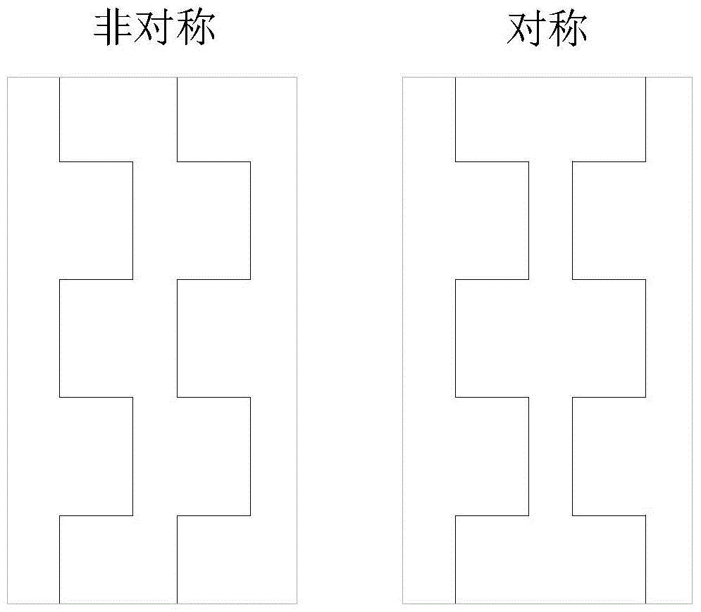
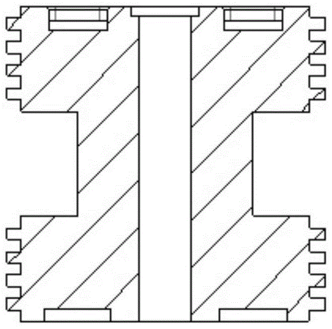
[0020] combine Figure 1-5 , the present invention mainly includes two parts: a mechanical stiffness system and an electromagnetic stiffness system. It should be noted that since some components belong to the mechanical stiffness system and as a part of the magnetic circuit, they also belong to the electromagnetic stiffness system, so they are mentioned repeatedly when introducing the structure.

[0021] The mechanical stiffness system is mainly composed of the mechanical spring 02, the mechanical spring 09 and the mechanical spring 12 through the combination of different components in parallel, which are introduced here. First, the support plate 11, the mechanical spring 12, the end cover 13, the housing 03 and the base 01 constitute the first subsystem; secondly, the support plate 11, the support column 10, the armature 04, the mechanical spring 09, the end cov...


PUM


Abstract

The invention aims at providing an electromagnetic semi-active vibration isolator achieving the quasi-zero rigidity characteristic through an asymmetric magnetic tooth structure. The electromagnetic semi-active vibration isolator comprises supporting plates, end covers, armatures, shells and bases. The end covers are arranged above the shells through screws. The bases are arranged below the shells through screws. The armatures are arranged in the shells. Shafts are installed in the centers of the armatures. The supporting plates are arranged above the end covers. First mechanical springs are arranged between the supporting plates and the end covers. Supporting columns are arranged in the first mechanical springs. The upper ends of the supporting columns are connected with the supporting plates through screws. The lower ends of the supporting columns penetrate the end covers and are connected with the armatures. First linear bearings and second linear bearings are arranged between the armatures and the shafts. Shaft sleeves are arranged between the first linear bearings and the second linear bearings. Second mechanical springs are arranged between the armatures and the end covers. Third mechanical springs are arranged between the armatures and the bases. The negative rigidity can be changed by adjusting the current, and accordingly system quasi-zero rigidity is easier to obtain.

Description

technical field [0001] The invention relates to a vibration isolator, specifically a semi-active vibration isolator. Background technique [0002] In the field of traditional passive vibration isolation design, in order to obtain a wider vibration isolation frequency band and better vibration isolation effect, the stiffness of the vibration isolator needs to be designed to be small enough, but a small vibration isolator stiffness is difficult to guarantee the entire The stability of the vibration isolation system, this contradiction has long been affecting the designers engaged in the field of vibration isolation. [0003] A vibration isolation system with quasi-zero stiffness characteristics can also be called a high static stiffness and low dynamic stiffness system. As the name implies, it can provide a higher static stiffness and a lower dynamic stiffness, the former is used to ensure that the vibration isolation system can have sufficient support stability in static sta...

Claims


Application Information

Patent Timeline
Patent Type & Authority Patents(China)
IPC IPC(8): F16F6/00
CPCF16F6/00
Inventor 刘学广韩超张佳琪梁伟龙杨铁军范朝阳吕绍平李文达叶天贵宿柱
Owner HARBIN ENG UNIV
Learn More