A Novel Electromagnetic Negative Stiffness Vibration Isolator with High Radial Stability

A technology of stability and negative stiffness, applied in the functional characteristics of springs/shock absorbers, magnetic springs, springs/shock absorbers, etc., can solve the problems of reducing the vibration isolation performance of the system, limiting negative stiffness, and unable to adjust negative stiffness. Achieve the effect of solving sliding friction or contact collision and improving radial stability

Active Publication Date: 2022-04-08
NUCLEAR POWER INSTITUTE OF CHINA
View PDF9 Cites 0 Cited by
  • Summary
  • Abstract
  • Description
  • Claims
  • Application Information

AI Technical Summary

Problems solved by technology

Traditional quasi-zero-stiffness vibration isolators mostly use a spring combination structure or a permanent magnet combination spring to achieve the negative stiffness effect. However, the non-adjustability of the achieved negative stiffness limits its application to a certain extent.
[0003] In order to solve the problem that the negative stiffness of the traditional quasi-zero stiffness vibration isolator cannot be adjusted, the invention authorized by the announcement number CN105485230B proposes an electromagnetic semi-active vibration isolator that uses an asymmetrical magnetic tooth structure to achieve quasi-zero stiffness characteristics. Its positive stiffness Provided by an array of helical springs, the negative stiffness is realized through an asymmetrically dislocated magnetic tooth structure, and the magnitude of the negative stiffness can be adjusted by changing the current, which can better solve the vibration problem of variable working conditions
[0004] The core technology of the negative stiffness achieved by this invention is to use "electromagnetic attraction" to construct the axially unstable force between the mover and the stator. However, there is a radial electromagnetic pull between the mover and the stator. Due to the processing and installation accuracy In the case of high current, the system is very prone to radial bias, and the radial stability is poor, which leads to contact friction or even collision between the mover and stator, which greatly reduces the vibration isolation performance of the system

Method used


Image

  • A Novel Electromagnetic Negative Stiffness Vibration Isolator with High Radial Stability
  • A Novel Electromagnetic Negative Stiffness Vibration Isolator with High Radial Stability

Examples


Embodiment 1

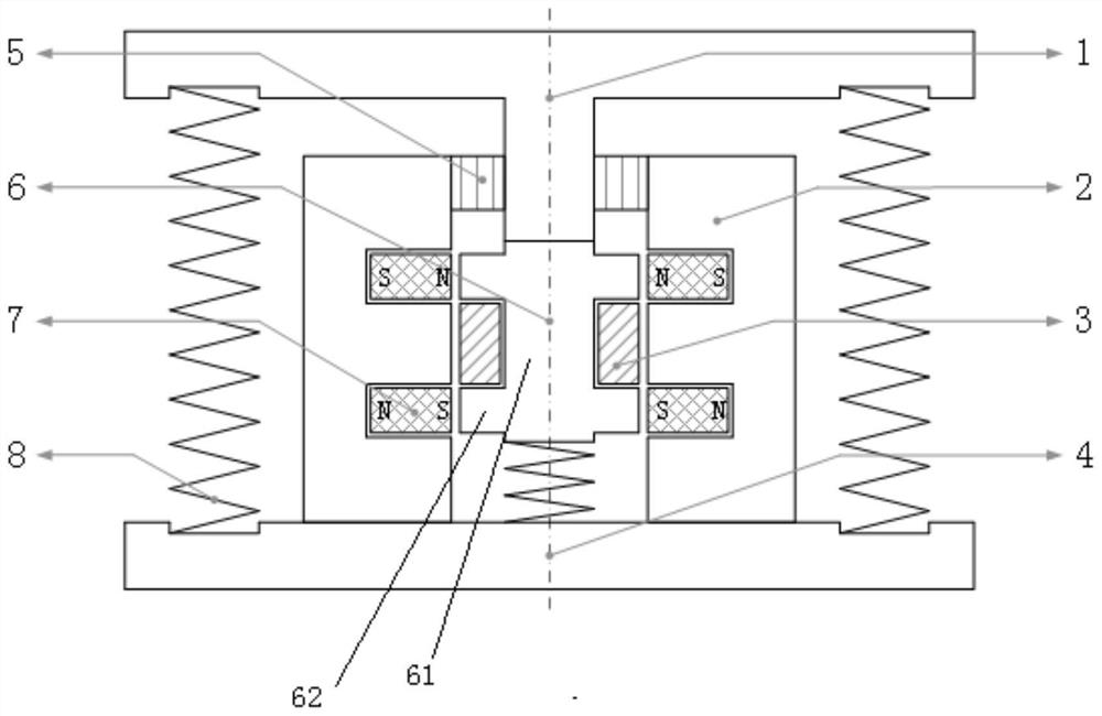
[0051] Such as figure 2 As shown, a new type of electromagnetic negative stiffness vibration isolator with high radial stability includes a stator housing 2, a mover arranged in the inner cavity of the stator housing 2 and movable along the longitudinal axis of the stator housing 2 6. Assembled under the mover 6, the first positive stiffness component that acts as a positive stiffness to the mover 6,

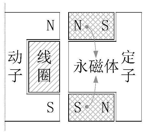
[0052] It also includes a coil 3 assembled on the outer wall of the mover 6 and wound around the longitudinal axis of the mover 6, and the mover 6 is made of high magnetic permeability material;

[0053] It also includes a permanent magnet 7 arranged on the first layer and a permanent magnet 7 arranged on the second layer along the longitudinal axis of the stator housing 2, which are assembled on the inner side wall of the stator housing 2, and the permanent magnet 7 on the first layer is connected to the second layer. The permanent magnetic field polarity end face of the perm...

Embodiment 2

[0060] Such as figure 2 Shown, on the basis of above-mentioned embodiment, preferably:

[0061] The mover 6 includes a magnetically permeable cylinder 61, a magnetically permeable ring protrusion 62 arranged on the first layer along the longitudinal axis, and a magnetically permeable ring protrusion 62 arranged on the second layer, wherein the magnetically permeable ring protrusion 62 of the first layer is arranged on the The magnetically permeable ring convex 62 of the second layer is integrally connected with the magnetically permeable cylinder 61,

[0062] Wherein the outer peripheral surface of the first layer of the magnetic permeable ring protrusion 62 is the first polarity end face of the mover 6, the outer peripheral surface of the second layer of the magnetic permeable ring protrusion 62 is the second polarity end face of the mover 6, the first polarity The polarity end face is directly opposite to the 7 polarity end faces of the permanent magnets of the first layer...

Embodiment 3

[0066] Such as figure 2 Shown, on the basis of above-mentioned embodiment, preferably:

[0067] Also includes a base 4, the lower bottom surface of the stator housing 2 is installed on the base 4;

[0068] The first positive stiffness component is a helical spring, and the helical spring is installed between the lower bottom surface of the mover 6 and the base 4 .

[0069] On the basis of above-mentioned technical scheme, preferred technical scheme is:

[0070] It also includes a support plate 1, the bottom surface of the support plate 1 has an extension,

[0071] Also includes a linear bearing 5, the linear bearing 5 is assembled on the upper port of the stator housing 2,

[0072] The extension part passes through the linear bearing 5 and is directly or indirectly connected to the upper end of the mover 6 .


PUM


Abstract

The invention discloses a novel electromagnetic negative stiffness vibration isolator with high radial stability, which comprises a stator housing (2), a mover (6), and a coil wound around the longitudinal axis of the mover (6). (3), also including permanent magnets (7) arranged on the first layer and permanent magnets (7) arranged on the second layer along the longitudinal axis of the stator housing (2), the permanent magnets (7) of the first layer and The permanent magnetic field polarity end face of the permanent magnet (7) of the 2nd layer faces radial direction, and the polarity of the permanent magnet (7) of the 1st layer is opposite to the polarity of the permanent magnet (7) of the 2nd layer; (6) The polarity of the upper end is the same as the polarity of the adjacent polarity end face of the permanent magnet (7) of the first layer; 7) The polarities of the adjacent polarity end faces are the same and mutually repel the energization direction. The repulsive force between the permanent magnet and the mover not only ensures the negative stiffness, but also restrains the bias of the mover.

Description

technical field [0001] The invention relates to the field of vibration isolator design, and relates to a novel electromagnetic negative stiffness vibration isolator with high radial stability. Background technique [0002] The quasi-zero stiffness vibration isolation technology can provide a lower dynamic stiffness on the premise of ensuring a higher static stiffness, thereby not only ensuring the static support stability of the system but also achieving a lower first-order natural frequency, and the low-frequency vibration isolation effect of the system better. Considering the superior performance of the quasi-zero stiffness vibration isolator, it has received more and more research and exploration in recent years. Traditional quasi-zero-stiffness vibration isolators mostly use a spring combination structure or a permanent magnet combination spring to achieve the negative stiffness effect, but the non-adjustability of the achieved negative stiffness limits its application ...

Claims


Application Information

Patent Timeline
Patent Type & Authority Patents(China)
IPC IPC(8): F16F6/00
CPCF16F6/00F16F2228/063F16F2228/066
Inventor 韩超李鑫刘桂祥张世伟沈双全林松卢军张鲲孙磊李朋洲
Owner NUCLEAR POWER INSTITUTE OF CHINA
Why Eureka
Try Eureka