A Streamlined Box Girder Eddy Vibration Suppression Structure

A streamlined, vortex-vibration technology, applied in bridges, bridge parts, bridge construction, etc., can solve problems such as the inability to effectively suppress vortex vibration, vortex-induced vibration, and propose a vibration-suppressing structure, so as to increase the comfort of use and reduce the amplitude of vortex vibration , to ensure the effect of structural safety

Inactive Publication Date: 2018-02-06
SOUTHWEST JIAOTONG UNIV
View PDF7 Cites 0 Cited by
  • Summary
  • Abstract
  • Description
  • Claims
  • Application Information

AI Technical Summary

Problems solved by technology

Usually, installing deflectors on both sides of the overhaul vehicle track at the bottom of the girder can suppress the vortex-induced vibration caused by the overhaul vehicle track, but when the railing on the bridge deck is the main cause of the vortex-induced vibration of the girder, this measure cannot effectively suppress the vortex vibration
At present, no vibration suppression structure has been proposed for the vortex induced vibration caused by bridge deck railings ( figure 2 )
In addition, the shape and structure of the anti-collision railings of highways and railway bridges in my country are determined by relevant specifications, and the purpose of vibration suppression cannot be achieved by directly modifying the structure of the railings themselves.

Method used


Image

  • A Streamlined Box Girder Eddy Vibration Suppression Structure
  • A Streamlined Box Girder Eddy Vibration Suppression Structure
  • A Streamlined Box Girder Eddy Vibration Suppression Structure

Examples


Embodiment 1

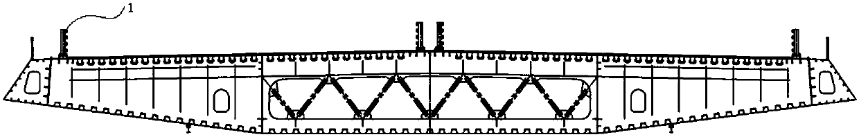
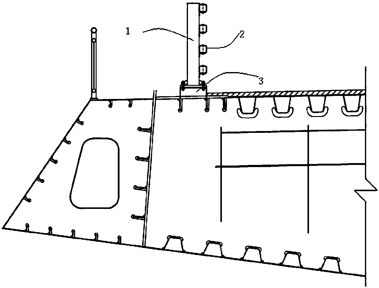
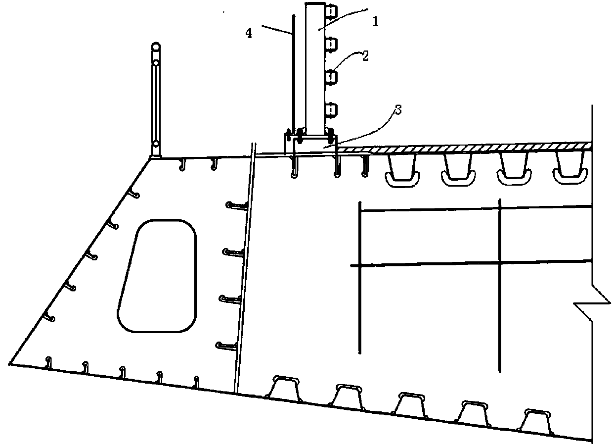
[0016] combine Figure 4a and Figure 4b as well as Figure 5a and Figure 5b It can be seen that a specific embodiment of the present invention is to suppress the vortex-induced vibration of the streamlined box girder of the long-span bridge by installing vortex vibration suppression plates along the span direction of the bridge at intervals between the anti-collision railing columns. In Fig. 4, 1 is the column of the anti-collision railing, 2 is the cross bar of the anti-collision railing, 3 is the support of the column of the anti-collision railing, and 4 is the vortex vibration suppression plate (referred to as the vibration suppression plate). The two ends of the vibration suppression plate are fixed on the support of the column of the anti-collision railing by bolts, and the distance between the vibration suppression plate and the column is 120-160 mm. H is the height of the column of the anti-collision railing, L is the distance between the columns of the anti-collis...

Embodiment 1

[0017] Example 1, B / L=3, D / H=1; H is 1420mm, L is 1500mm, D is 1420mm, B is 4500mm, and the distance between the damping plate and the column is 120mm.

Embodiment 2

[0018] Embodiment 2, B / L=4, D / H=0.5; All the other are the same as embodiment 1.


PUM


Abstract

The invention discloses a streamlined box girder vortex vibration suppression structure, which is attached to the arrangement of anti-collision railings on the bridge deck and is used to suppress the vortex-induced vibration of the streamlined box girder of a long-span bridge. It is characterized in that the anti-collision railings on both sides of the bridge deck A vertical vortex vibration suppression plate is installed at a certain interval at the support of the column. The distance between the vortex vibration suppression plate and the edge of the column is 120mm to 160mm; the width of each vibration suppression plate is the same as the distance L between the columns of the anti-collision railing. The plate height D needs to meet 0.5≤D≤H, and the installation distance B of the vortex vibration suppression plate needs to meet 3≤B / L≤5, and B / L takes an integer. The structure of the invention overcomes the disadvantage that the vortex-induced vibration of the main girder caused by the streamlined box girder deck railing cannot be suppressed by directly modifying the railing itself. Its aerodynamic layout starts from the source of vortex-induced vibration and fundamentally weakens the span-to-span correlation of the vortex-induced force of the main girder, thereby reducing the vortex vibration amplitude of the main girder, increasing the comfort of the bridge, and ensuring the streamlined box Structural safety of beam main beam.

Description

technical field [0001] The invention relates to the field of bridge wind engineering, in particular to the field of vortex-induced vibration control of a streamlined box girder of a long-span bridge. Background technique [0002] The streamlined box girder commonly used on long-span bridges has a good aerodynamic shape ( figure 1 ), and the aerodynamic stability is good. When the main beam is not equipped with auxiliary structures such as railings and maintenance tracks, the phenomenon of vortex-induced vibration rarely occurs. However, when the auxiliary facilities are installed on the main girder, the aerodynamic shape of the streamlined box girder changes, which causes vortex-induced vibration of the main girder. Vortex-induced vibration will affect the comfort of the bridge, and even affect the structural safety in severe cases. It is necessary to find reasonable and effective vibration suppression measures. [0003] Existing research results show that the main reasons...

Claims


Application Information

Patent Timeline
Patent Type & Authority Patents(China)
IPC IPC(8): E01D19/00E01D2/04
CPCE01D2/04E01D19/00
Inventor 孙延国李明水廖海黎胡辉跃伍波
Owner SOUTHWEST JIAOTONG UNIV
Why Eureka
Try Eureka