AI technical title is built by Patsnap AI team. It summarizes the technical point description of the patent document.
A technology of flying umbrellas and blades, applied in the field of layered products
Active Publication Date: 2016-05-04
王锦祥
View PDF6 Cites 1 Cited by
Summary
Abstract
Description
Claims
Application Information
AI Technical Summary
This helps you quickly interpret patents by identifying the three key elements:
Problems solved by technology
Method used
Benefits of technology
Problems solved by technology
[0002] Existing blades are divided into two types, blades with leakage holes and blades without leakage holes. Neither of the above two types of blades can form a large pressure difference between the upper and lower sides of the blade.
Method used
Image
Click on the blue label to locate the original text in one second.
Reading with bidirectional positioning of images and text.
Examples
Embodiment 1
[0060] Embodiment 1, with reference to Figure 1 to Figure 5 .
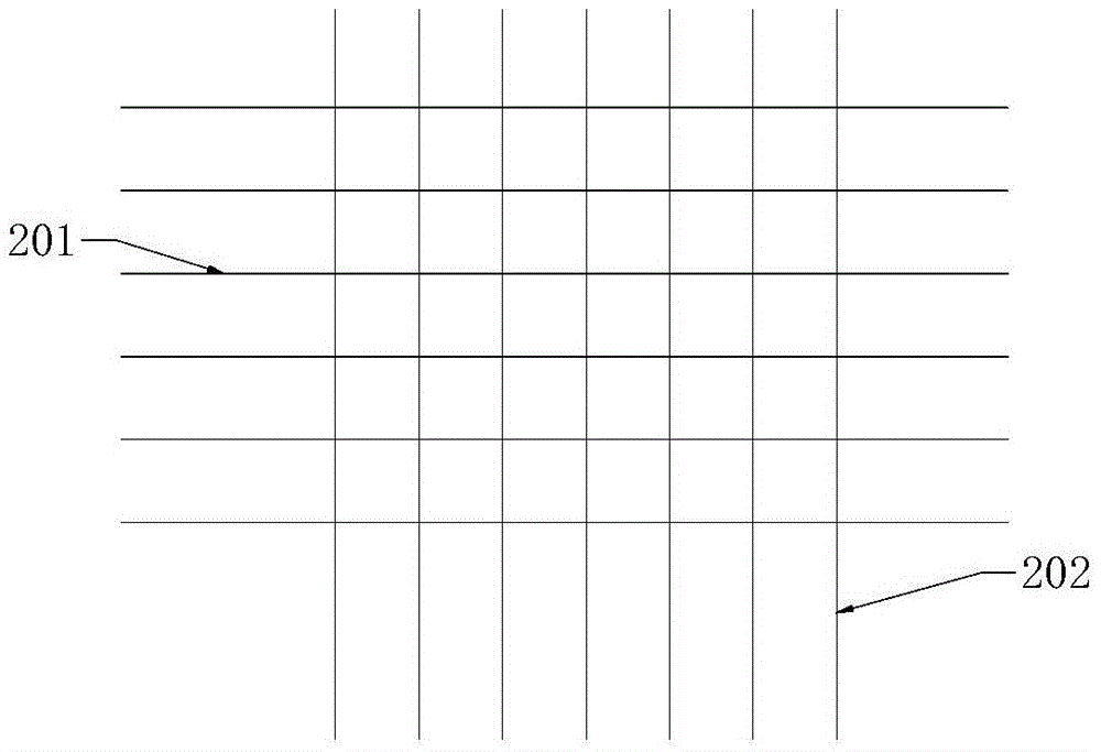
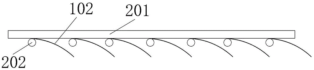
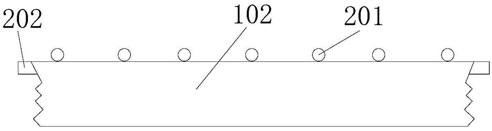
[0061] Such as figure 1 , figure 2 , image 3 , Figure 4 and Figure 5 As shown, the blade 102 cloth provided by the present invention includes an upper layer wire rope 201 and a lower layer wire rope 202, the lower layer wire rope 202 includes a plurality of first wire ropes arranged side by side, the upper layer wire rope 201 includes a plurality of second wire ropes, and a plurality of first wire ropes. Two wire ropes are laid crosswise on the upper side of multiple first wire ropes; one end of each blade 102 is glued between the first wire rope and the second wire rope, and the other end is a movable end and is located below the first wire rope.
[0062] During the specific production, the lower layer wire rope 202 is first laid, and then the plurality of blades 102 are glued to the upper side of the first wire rope one by one, and the blade 102 is parallel to the plane where the grid blade cloth is lo...
Embodiment 2
[0070] Example 2, such as Figure 6 to Figure 13 .
[0071] Such as Figure 6 , Figure 7 , Figure 8 and Figure 9 As shown, the paraglider provided by this embodiment includes a support frame 101, the support frame 101 is provided with a parachute surface and a support base, the parachute surface is located above the support base, and the support base is used to provide a standing position for the pilot;
[0072] The flying umbrella surface comprises an umbrella surface frame and the mesh blade cloth according to any one of claims 1-4, and the mesh blade cloth is arranged on the umbrella surface frame.
[0073] The support frame 101 is used to install the paraglider surface and the support seat, the paraglider surface provides the lift for the paraglider to glide, and the support seat provides a standing position for the glider. The blades 102 can swing at a certain angle relative to the canopy frame, and when the parachute is in a static state, the blades 102 are in a ...
Embodiment 3
[0083] Example 3, such as Figure 14 and Figure 15 .
[0084] The windmill provided in this embodiment, such as Figure 14 and 15 As shown, it includes a rotating shaft 203, a mounting frame 204, and any one of the mesh blade cloths in claims 1-4, the mounting frames 204 are provided with at least three, and one side edge of each mounting frame 204 is fixed to the rotating shaft 203, Each installation frame 204 is correspondingly provided with a mesh blade cloth.
[0085] Regardless of the wind direction, there is always a grid blade cloth on one installation frame 204 in a windward closed state, and the other two grid blade cloths are in an open state, thereby forming an asymmetric resistance to make the windmill rotate, and the windmill can also be provided with multiple installation frames 204. This type of windmill is more efficient than other types of windmills and does not cost much. It is also possible to form a windmill group, which is connected with ropes at th...
PUM
Abstract
The invention provides a piece of grid blade cloth, a paragliding and a windmill, and belongs to the field of layered products. The grid blade cloth comprises an upper layer rope and a lower layer rope, wherein the lower layer rope comprises a plurality of first ropes which are arranged in parallel; the upper layer rope comprises a plurality of second ropes; the second ropes are paved on the upper sides of the first ropes in a cross manner; one end of each blade is adhered between the corresponding first rope and the corresponding second rope; the other end of each blade functions as a moveable end and is positioned below the corresponding first rope. The grid blade cloth can be applied to a plurality of fields such as the surface of the flight umbrella, the blade surface of the windmill rotating horizontally, and water sports shoes disclosed by the invention. The paragliding and the windmill comprise the grid blade cloth, and the paragliding can fly without power and can be also driven to fly by engines. According to the technical scheme, the invention provides the grid blade cloth through which fluid can only pass in one direction, relatively large pressure difference can be formed between two sides of the grid blade cloth, the lifting power can be effectively provided by virtue of the pressure difference, and the grid blade cloth is simple in principle and low in manufacturing cost.
Description
technical field [0001] The invention relates to the field of layered products, in particular to a mesh blade cloth, a parachute and a windmill. Background technique [0002] Existing blades are divided into two types, blades with leakage holes and blades without leakage holes, both of which cannot form a large pressure difference between the upper and lower sides of the blade. Contents of the invention [0003] The purpose of the present invention is to provide a mesh blade cloth, which can form a larger pressure difference on both sides to provide a larger lifting force. [0004] The object of the present invention is to provide a flying parachute capable of obtaining greater lifting force. [0005] The purpose of the present invention is to provide a windmill with better rotation efficiency. [0006] The present invention is achieved like this: [0007] The mesh blade cloth provided by the present invention includes an upper layer wire rope and a lower layer wire rope...
Claims
Application Information
Patent Timeline
Application Date:The date an application was filed.
Publication Date:The date a patent or application was officially published.
First Publication Date:The earliest publication date of a patent with the same application number.
Issue Date:Publication date of the patent grant document.
PCT Entry Date:The Entry date of PCT National Phase.
Estimated Expiry Date:The statutory expiry date of a patent right according to the Patent Law, and it is the longest term of protection that the patent right can achieve without the termination of the patent right due to other reasons(Term extension factor has been taken into account ).
Invalid Date:Actual expiry date is based on effective date or publication date of legal transaction data of invalid patent.

