Lamp holder rotating structure and LED lamp

A technology of lamp head rotation and lamp head cover, applied in the field of lighting, can solve the problems of relative distance change, non-compliance with the detection standard of LED lamps, etc., and achieve the effect of meeting the detection standard

Inactive Publication Date: 2016-05-04
SHENZHEN LONGHORN INTELLIGENT INSTR TECH CO LTD
View PDF8 Cites 2 Cited by
  • Summary
  • Abstract
  • Description
  • Claims
  • Application Information

AI Technical Summary

Problems solved by technology

[0002] When using an LED lamp, it is often necessary to adjust its lighting direction according to the use environment. When the existing rotating structure of the lamp cap rotates, the po

Method used


Image

  • Lamp holder rotating structure and LED lamp
  • Lamp holder rotating structure and LED lamp
  • Lamp holder rotating structure and LED lamp

Examples


Example Embodiment

[0030] In order to make the technical problem solved by the present invention, the technical solution adopted and the technical effect achieved clearer, the following technical solutions are adopted:

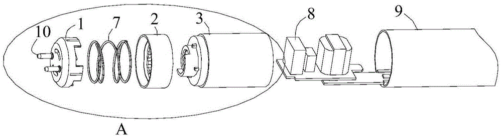
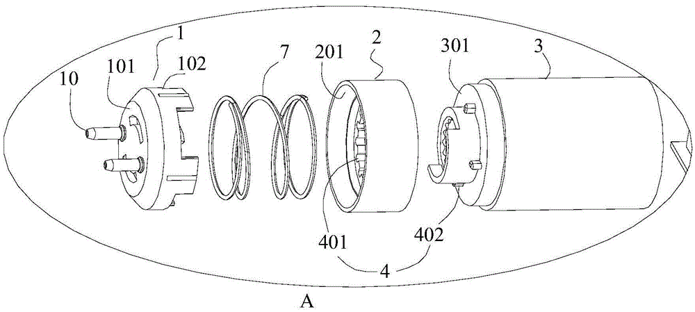
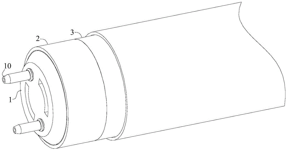
[0031] Please refer to Figure 1 to Figure 18 . refer to Figure 1 to Figure 3 , the first embodiment of the present invention provides a lamp holder rotating structure, including lamp cap 1, dial 2 and power supply compartment 3; lamp cap 1 and dial 2 are slidably connected; lamp cap 1 and power supply compartment 3 are rotatably connected , the dial 2 and the power supply compartment 3 are limited by the first positioning structure 4, and the first positioning structure 4 includes a first tooth slot 401 and a first positioning protrusion 402 that is clamped into the first tooth slot 401;

[0032] refer to Figure 4 and Figure 5 , when the dial 2 is close to the power supply compartment 3, the first positioning protrusion 402 is stuck into the first tooth slot 401, and the...


PUM


Abstract

The invention discloses a lamp holder rotating structure and an LED lamp with the lamp holder rotating structure. The lamp holder rotating structure comprises a lamp holder cover, a dial and a power source bin. The lamp holder cover and the dial are in sliding connection. The lamp holder cover is rotatably connected with the power source bin. The dial and the power source bin are limited through a first locating structure, and the first locating structure comprises first tooth grooves and first locating protrusions clamped into the first tooth grooves. When the dial is close to the power source bin, the first locating protrusions are clamped into the first tooth grooves, the dial and the power source bin cannot relatively rotate, and the lamp holder cover and the power source bin cannot relatively rotate. When the dial is pushed away from the power source bin, the first locating protrusions are separated out of the first tooth grooves, the dial and the power source bin can relatively rotate, and the lamp holder cover and the power source bin can relatively rotate. The dial and the power source bin are relatively fixed or rotate by changing the position of the dial, relative fixing or rotating of the lamp holder cover and the power source bin is achieved, the relative distance between the lamp holder cover and the lamp holder bin is not changed, and relevant detecting standards are met.

Description

technical field [0001] The invention relates to the field of lighting, in particular to a lamp holder rotating structure and an LED lamp. Background technique [0002] When the LED lamp is in use, it is often necessary to adjust its lighting direction according to the use environment. When the existing lamp head rotating structure rotates, the power supply compartment and the lamp cap must be separated, so that the relative distance between the power supply compartment and the lamp cap is changed. Relevant LED lamp inspection standards. SUMMARY OF THE INVENTION [0003] The first objective of the present invention is to provide a lamp cap rotation structure, during rotation, the relative distance between the power supply compartment and the lamp cap cover of the lamp cap rotation structure does not change. [0004] For this purpose, the present invention adopts the following technical solutions: [0005] A lamp holder rotating structure comprises a lamp cap, a dial and a...

Claims


Application Information

Patent Timeline
IPC IPC(8): F21K9/272F21K9/278F21Y103/00F21Y115/10
CPCF21V21/00F21V21/002F21V23/00
Inventor 李国超朱志青罗吉国陈兴国杨海涛
Owner SHENZHEN LONGHORN INTELLIGENT INSTR TECH CO LTD
Why Eureka
Try Eureka