

Method for acquiring optimal focal plane distance of laser direct imaging equipment
A technology of laser direct imaging and best focal plane, which is applied in the direction of microlithography exposure equipment, optics, photoplate making process of pattern surface, etc. It can solve the problems of inaccuracy, incomplete exposure of dry film, and affecting image quality of graphics, etc. , to achieve the effect of improving detection efficiency and accuracy and reducing the risk of scrapping
- Summary
- Abstract
- Description
- Claims
- Application Information
AI Technical Summary
Problems solved by technology
Method used
Image

Examples
Embodiment 1
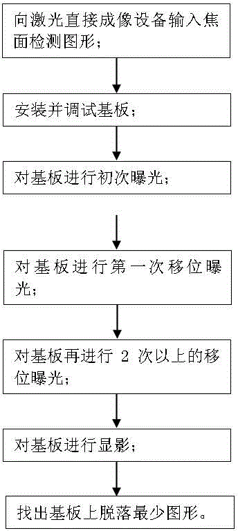
[0034] The method for obtaining the optimal focal plane distance of the laser direct imaging device is specifically carried out as follows:
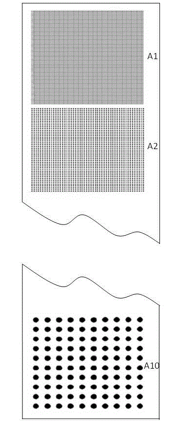
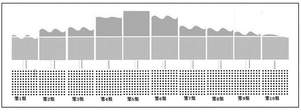
[0035] Step 1: The operator inputs a focal plane detection pattern to the laser direct imaging device; the focal plane detection pattern contains 10 exposure patterns;
[0036] Step 2: In a yellow light environment, place a substrate on the exposure workbench of the laser direct imaging equipment. The substrate is a PCB board covered with a layer of photosensitive dry film; the photosensitive dry film is SL1329 produced by Hitachi The dry film; Subsequently, adjust the relative distance between the laser head of the laser direct imaging device and the exposure workbench to be 5.00mm;
[0037]Step 3: In the environment of yellow light, let the laser generated by the laser head of the laser direct imaging device directly project the shape of the focal plane detection pattern entered in step 1 on the substrate, that is, complete the first e...
Embodiment 2
[0050] The method for obtaining the optimal focal plane distance of the laser direct imaging device, specifically operates as follows:
[0051] Step 1: making a focal plane detection graphics board; the focal plane detection graphics board contains 10 exposure graphics;
[0052] Step 2: In a yellow light environment, place a substrate on the exposure workbench of the laser direct imaging equipment, and the substrate is a PCB board covered with a layer of photosensitive dry film; the photosensitive dry film is YQ40PN produced by Asahi Kasei The dry film; Subsequently, adjust the relative distance between the laser head of the laser direct imaging device and the exposure workbench to be 2.00mm;
[0053] Step 3: In the environment of yellow light, let the laser generated by the laser head of the laser direct imaging device directly project the shape of the focal plane detection pattern entered in step 1 on the substrate, that is, complete the first exposure of the substrate , at...
PUM
| Property | Measurement | Unit |
|---|---|---|
| Diameter | aaaaa | aaaaa |
Abstract
Description
Claims
Application Information