
Pier plate of water control gate

A technology for pier boards and gates, which is applied in ship locks, artificial waterways, water conservancy projects, etc., and can solve problems such as expensive heating current is not easy to obtain

Active Publication Date: 2017-12-05
亨利·欧伯梅尔
View PDF15 Cites 0 Cited by
  • Summary
  • Abstract
  • Description
  • Claims
  • Application Information

AI Technical Summary

Problems solved by technology

Electricity for heating may not be readily available and the amount of electricity (kW-hours) required to keep the gate system operational throughout the winter is generally expensive

Method used


Image

  • Pier plate of water control gate
  • Pier plate of water control gate
  • Pier plate of water control gate

Examples


Embodiment Construction

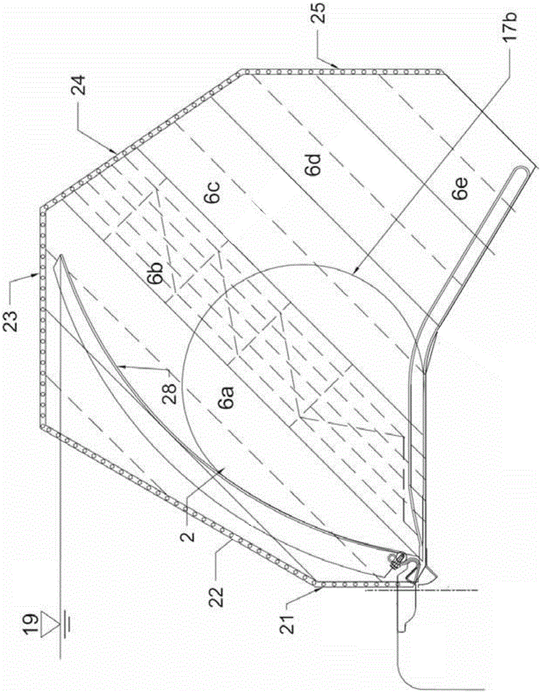
[0035] see figure 1 , the abutment slats 6a, 6b, 6c, 6d and 6e are connected to the concrete abutment 19. The inflated bladder 17b operates the ram 28 to which the abutment seal 2 is attached. The upstream edge of the abutment strip 6a is clamped to the concrete abutment 19 by clamps 21 and 22 . The remaining edges of the abutment strips 6 a , 6 b , 6 c , 6 d and 6 e are secured by clamps 23 , 24 and 25 . In addition to the water control gate shown in the present invention, the abutment plate of the present invention can also be widely used in various water control gates.

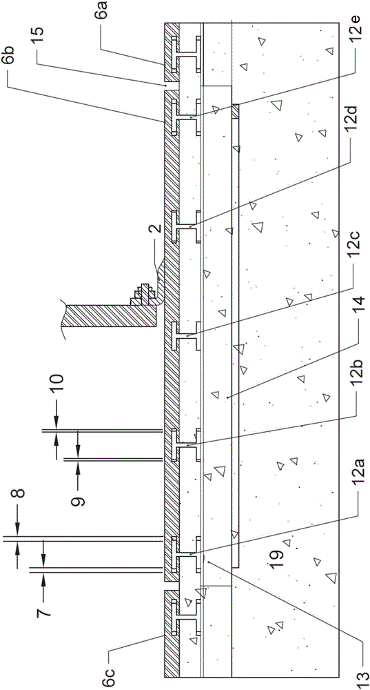
[0036] see now figure 2, shows a cross-sectional view of the abutment plate assembly. Guide rails 12a , 12b , 12c , 12d and 12e secure the abutment slat 6b to the concrete pier 19 . The gaps 7, 8, 9 and 10 vary in proportion to their distance from the center rail 12c, which only needs to provide the minimum gap. The guide rails are connected to spacer members 13 , which in turn are connected to brace...


PUM


Abstract

The invention relates to an anti-friction and ice-resistant water control gate abutment plate. Under the condition of not damaging the concrete, the abutment plate can be placed between the abutment plate assembly and the concrete abutment, or between the abutment plate assembly There is substantial relative thermal motion between the piers to which the pier plate assembly is attached. Ease of maintenance, tight sealing, and resistance to splinter damage are also disclosed.

Description

technical field [0001] The present invention relates to an abutment plate for a water control gate, especially suitable for controlling river courses and canals, in particular where such gates are subjected to freezing conditions. Background technique [0002] Ultra-high molecular weight (UHMW) polyethylene can be used as the abutment plate of the bottom hinged water control gate. Such (one-piece) abutment plates may be bolted loosely using closely spaced bolts in small dimensions such as 1-2 meters wide. The close spacing of the bolts prevents thermal buckling of the abutment plate, however, the gaps between the bolts and the gaps between the holes in the UHMW abutment plate allow limited thermal movement of the abutment plate relative to the underlying structure. The clearance of the bolts prevents excessive stress due to thermal dimensional changes of the abutment plate. Alternatively, the UHMW abutment plate can be secured to the concrete abutment with springs. The ra...

Claims


Application Information

Patent Timeline
Patent Type & Authority Patents(China)
IPC IPC(8): E02B7/54
CPCE02B7/54E02C1/08E02B3/16E02B17/0021E02B5/082E02B7/28E02B7/50
Inventor 亨利·欧伯梅尔罗伯特·埃克曼
Owner 亨利·欧伯梅尔
Features
  • Generate Ideas
  • Intellectual Property
  • Life Sciences
  • Materials
  • Tech Scout
  • Unparalleled Data Quality
  • Higher Quality Content
  • 60% Fewer Hallucinations
Learn More