Zoom lens and optical device

A zoom lens and lens group technology, applied in optics, optical components, instruments, etc., can solve the problems of small F value, large size of optical system, difficult to realize F value optical system structure, etc., and achieve small F value and good optical performance Effect

Active Publication Date: 2019-07-19
FUJIFILM CORP
View PDF10 Cites 0 Cited by
  • Summary
  • Abstract
  • Description
  • Claims
  • Application Information

AI Technical Summary

Problems solved by technology

[0010] However, the F value of the zoom lenses described in Patent Documents 1 to 3 is 4 or more, so it cannot be considered that the F value is small.
In the above-mentioned lens system, the second lens group of the moving group arranged next to the reduction side of the first lens group, which is the fixed group, is set as a negative lens group, so it is difficult to realize the structure of an optical system with a small F value.
In the zoom lens described in Patent Document 4, the size of the optical system is large relative to the focal length, and it cannot be considered that it can meet the demands for miniaturization in recent years.

Method used


Image

  • Zoom lens and optical device
  • Zoom lens and optical device
  • Zoom lens and optical device

Examples


Embodiment 1

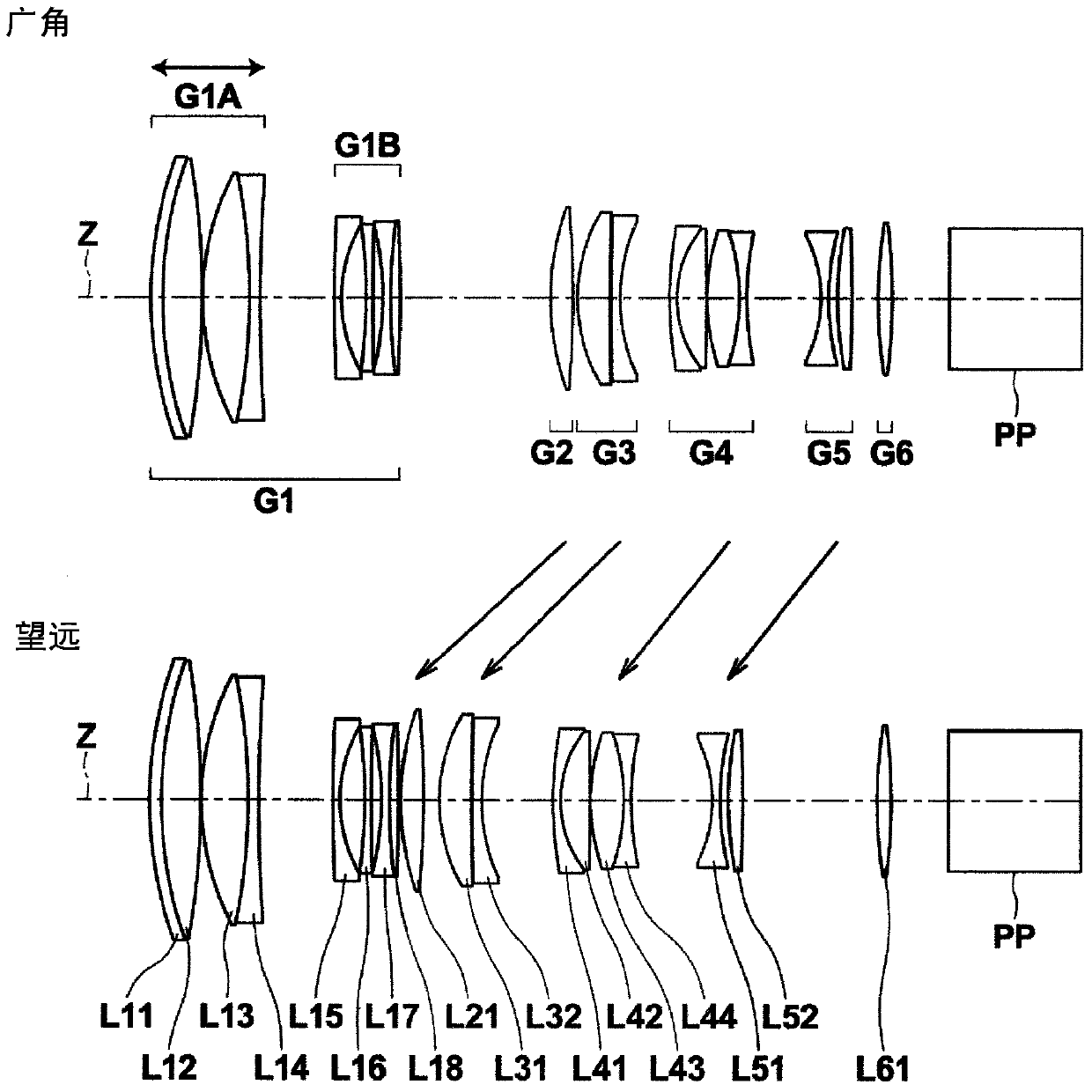
[0100] The structural diagram of the zoom lens of embodiment 1 is as figure 1 , figure 2 shown. The zoom lens of Example 1 has a six-group structure composed of the first lens group G1 to the sixth lens group G6. The first lens group G1 has negative refractive power as a whole, and is composed of a front group G1A and a rear group G1B. The front group G1A is composed of lenses L11 to L14. The rear group G1B is composed of lenses L15 to L18. The second lens group G2 is composed of only the lens L21. The third lens group G3 is composed of lenses L31 to L32. The fourth lens group G4 is composed of lenses L41 to L44. The fifth lens group G5 is composed of lenses L51 to L52. The sixth lens group G6 is composed of only the lens L61. Focusing is performed by moving only the front group G1A in the optical axis direction.

[0101] Table 1 and Table 2 respectively show the basic lens data and the value of the variable surface interval of the zoom lens of Example 1. In the Si ...

Embodiment 2

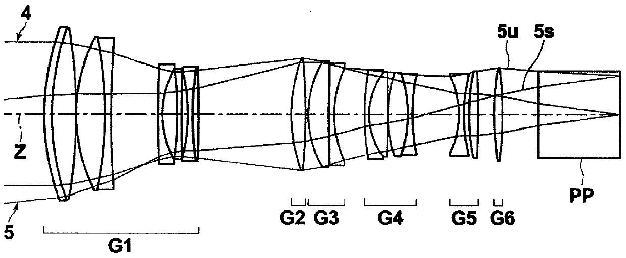
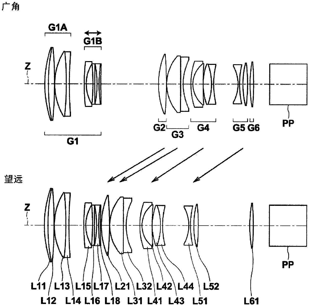
[0115] image 3 A lens configuration diagram showing the zoom lens of Example 2, Figure 4 The optical path diagram at the wide-angle end is shown. The zoom lens of Example 2 has a six-group structure composed of the first lens group G1 to the sixth lens group G6. The first lens group G1 has negative refractive power as a whole, and is composed of a front group G1A and a rear group G1B. The front group G1A is composed of lenses L11 to L14. The rear group G1B is composed of lenses L15 to L18. The second lens group G2 is composed of only the lens L21. The third lens group G3 is composed of lenses L31 to L32. The fourth lens group G4 is composed of lenses L41 to L44. The fifth lens group G5 is composed of lenses L51 to L52. The sixth lens group G6 is composed of only the lens L61. Focusing is performed by moving only the rear group G1B in the optical axis direction.

[0116] Table 3 and Table 4 respectively show the basic lens data and the value of the variable surface i...

Embodiment 3

[0125] Figure 5 A lens configuration diagram showing the zoom lens of Example 3, Figure 6 The optical path diagram at the wide-angle end is shown. The zoom lens of Example 3 has a five-group structure composed of the first lens group G1 to the fifth lens group G5. The first lens group G1 has negative refractive power as a whole, and is composed of a front group G1A and a rear group G1B. The front group G1A is composed of lenses L11 to L14. The rear group G1B is composed of lenses L15 to L18. The second lens group G2 is composed of only the lens L21. The third lens group G3 is composed of lenses L31 to L32. The fourth lens group G4 is composed of lenses L41 to L46. The fifth lens group G5 is composed of only the lens L51. A floating focus method in which focusing is performed by moving the front group G1A and the rear group G1B in the direction of the optical axis so that the distance between the front group G1A and the rear group G1B changes.

[0126] Table 5 and Tab...


PUM


Abstract

The present invention provides a zoom lens with a long focal point, small size, small F value, and good optical performance, and an optical device including the zoom lens. The zoom lens has a first lens group (G1) arranged on the most magnification side and fixed when changing magnification, and a positive optical lens group (G1) arranged adjacent to the reduction side of the first lens group (G1) and moving when changing magnification. focal power of the second lens group (G2). The first lens group (G1) is substantially composed of a front group (G1A) having positive refractive power and a rear group (G1B) having negative refractive power in order from the magnification side. Focusing is performed by changing the interval between the front group (G1A) and the rear group (G1B). The zoom lens satisfies the conditional expression (1) related to the focal length (f1b) of the rear group (G1B) and the focal length (ft) of the entire system at the telephoto end: -0.35≤f1b / ft<0.

Description

technical field [0001] The present invention relates to a zoom lens and an optical device, and more specifically, to a zoom lens suitable as a projection optical system used in a projection display device or an imaging optical system used in a digital camera, video camera, etc. And an optical device equipped with the zoom lens. Background technique [0002] Conventionally, cameras in the above-mentioned fields have used an imaging optical system that captures an image of a subject on the magnification side and forms an image on an imaging element on the reduction side. In addition, conventionally, in a projection display device, a projection optical system for projecting an optical image of light modulated by a modulation element disposed on the reduction side toward the enlargement side is used. In such a projection optical system and an imaging optical system, a zoom lens capable of realizing various focal lengths with a single optical system is mainly used. [0003] Amo...

Claims


Application Information

Patent Timeline
Patent Type & Authority Patents(China)
IPC IPC(8): G02B15/16
CPCG02B15/142G02B15/1465G02B27/646
Inventor 山本力
Owner FUJIFILM CORP
Why Eureka
Try Eureka