Camera lens and camera device

A camera lens, lens technology, applied in optical components, instruments, optics, etc., can solve the problem of small F value of the lens system, and achieve the effect of small F value, high optical performance, and wide field of view.

Active Publication Date: 2020-02-07
FUJIFILM CORP
View PDF7 Cites 0 Cited by
  • Summary
  • Abstract
  • Description
  • Claims
  • Application Information

AI Technical Summary

Problems solved by technology

[0006] However, the F value of the lens system described in Patent Document 1 cannot be said to be sufficiently small, and there is room for improvement in terms of aberration correction, and further performance enhancement is required to meet recent expectations.

Method used


Image

  • Camera lens and camera device
  • Camera lens and camera device
  • Camera lens and camera device

Examples


Embodiment 1

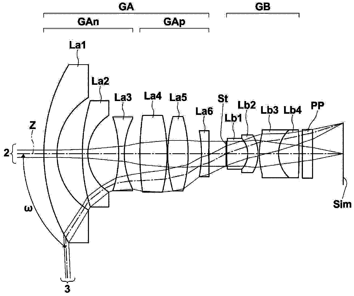
[0122] The structure of the imaging lens of embodiment 1 is as follows figure 1 shown. It should be noted, figure 1 The detailed description of each lens group and each lens in the structure is as above, so repeated description is omitted here.

[0123] Table 1 shows the lens data of the imaging lens of Example 1. The Si column of Table 1 shows the i-th (i=1, 2, 3, ...) surface numbers that increase sequentially toward the image side, with the object-side surface of the most object-side component as the first , the Ri column shows the radius of curvature of the i-th surface, and the Di column shows the distance between the i-th surface and the i+1-th surface on the optical axis Z. It should be noted that the sign of the radius of curvature is positive in the case of a surface shape with a convex surface facing the object side, and negative in the case of a surface shape with a convex surface facing the image side. The value in the lowermost column of Di is the distance bet...

Embodiment 2

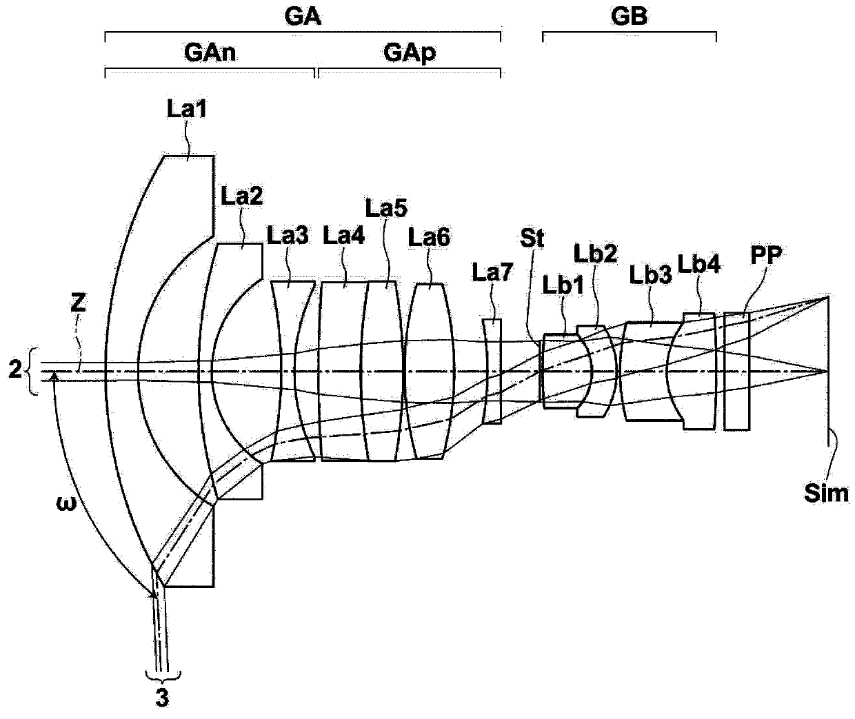
[0133] The structure of the imaging lens of embodiment 2 is as follows figure 2 shown. In the imaging lens of Example 2, the front negative lens group GAn is composed of lenses La1 to La3, the front positive lens group GAp is composed of lenses La4 to La7, and the rear group GB is composed of lenses Lb1 to Lb4. Table 2 shows the lens data of the imaging lens of Example 2. Figure 7 Each aberration diagram in the state where the imaging lens of Example 2 is in focus on an object at infinity is shown in .

[0134] 【Table 2】

[0135] Example 2

[0136] f=1.00, Bf=2.26, FNo.=2.55, 2ω=185.0°

[0137] Si Ri Di Ndj νdj ΔθgFj 1 9.1047 0.7055 1.90366 31.31 0.00391 2 3.4197 1.3197 3 9.2525 0.2864 1.85026 32.27 0.00364 4 2.3784 1.5137 5 -8.5657 0.2863 1.61800 63.33 0.00509 6 4.0610 0.5243 7 22.9665 0.9248 1.51633 64.14 -0.00239 8 11.2072 0.9183 1.84666 23.78 0.01751 9 -11.0359 ...

Embodiment 3

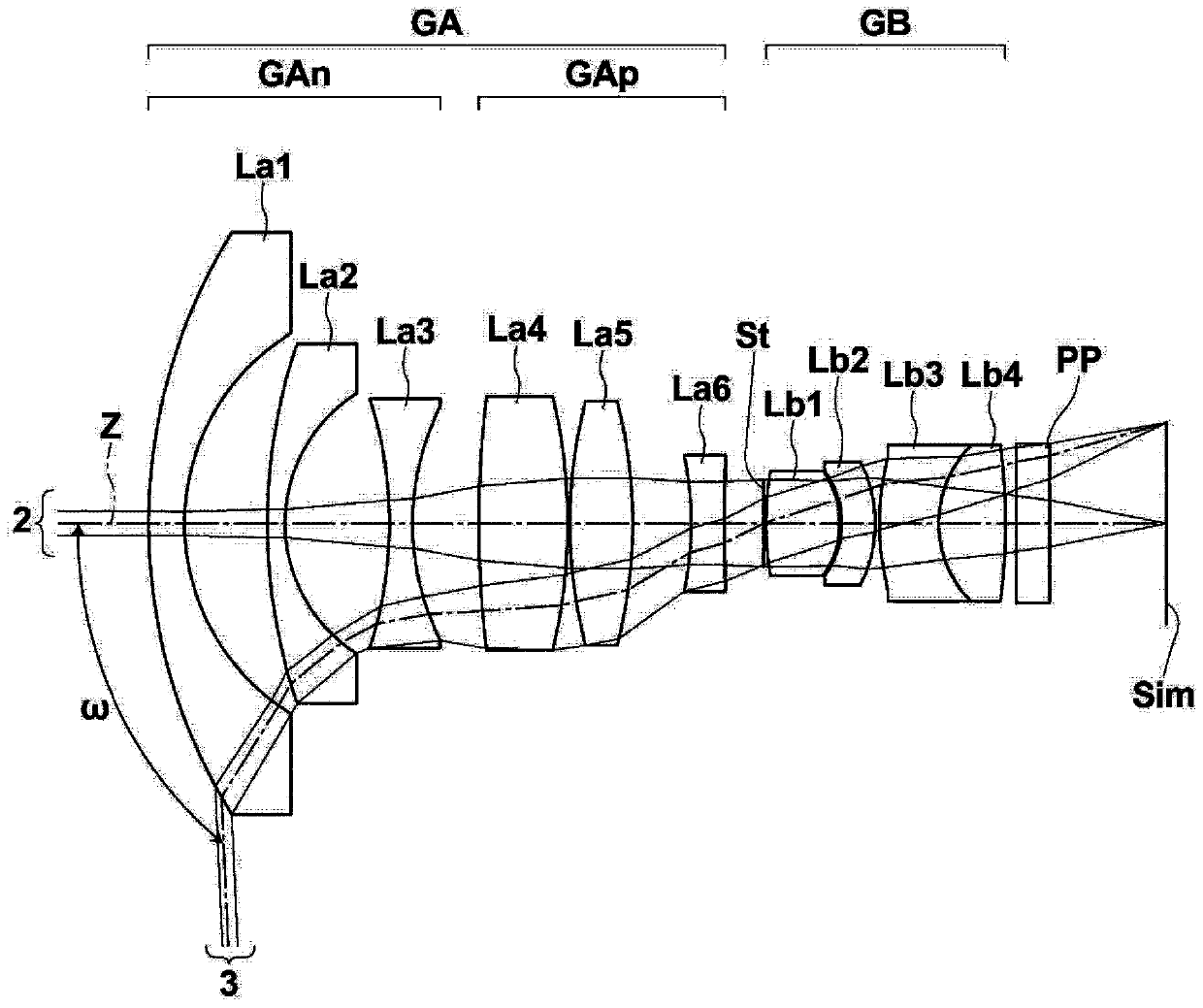
[0139] The structure of the imaging lens of embodiment 3 is as image 3 shown. In the imaging lens of Example 3, the front negative lens group GAn is composed of lenses La1 to La3, the front positive lens group GAp is composed of lenses La4 to La6, and the rear group GB is composed of lenses Lb1 to Lb4. Table 3 shows the lens data of the imaging lens of Example 3. Figure 8 Each aberration diagram in the state where the imaging lens of Example 3 is in focus on an object at infinity is shown in .

[0140] 【table 3】

[0141] Example 3

[0142] f=1.00, Bf=2.41, FNo.=2.55, 2ω=185.0°

[0143] Si Ri Di Ndj νdj ΔθgFj 1 8.7150 0.5788 1.90366 31.31 0.00391 2 3.5608 1.3343 3 8.8901 0.2861 1.85026 32.27 0.00364 4 2.4650 1.6807 5 -6.3968 0.3710 1.61800 63.33 0.00509 6 4.1489 1.0731 7 16.2728 1.4308 1.80518 25.42 0.01576 8 -8.7085 0.0361 9 7.6986 1.0062 1.80610 40.93 -0.0051...


PUM


Abstract

An imaging lens consists of, in order from the object side, a front group having a negative refractive power, a stop, and a rear group having a positive refractive power. The front group consist of a front-group negative lens group that consists of three negative lenses and has a negative refractive power, and a front-group positive lens group that includes one positive lens and one negative lens and has a positive refractive power, where the negative lens is disposed at the most image-side position. The rear group includes two positive lenses and two negative lenses. The imaging lens satisfies condition expression (1): 0.95<−fAn / f<2, where fAn is a focal length of the front-group negative lens group, and f is a focal length of the entire system.

Description

technical field [0001] The present invention relates to an imaging lens and an imaging device, and more specifically, to an imaging lens suitable for a surveillance camera, a vehicle camera, a digital camera, and the like, and an imaging device including the imaging lens. Background technique [0002] In surveillance cameras and vehicle cameras, wide-angle imaging lenses tend to be used in order to be able to capture a wide range. In order to reduce or eliminate dead angles, sometimes a lens system with a full field of view close to 180° is used. As such a wide-angle lens system, for example, a fisheye lens described in Patent Document 1 below is known. [0003] prior art literature [0004] Patent Document 1: Japanese Patent Publication No. 63-3286 [0005] Imaging lenses used in imaging devices in the above-mentioned fields are not only required to be wide-angle, but also small in size in consideration of installation space and portability, and small in F value in order ...

Claims


Application Information

Patent Timeline
Patent Type & Authority Patents(China)
IPC IPC(8): G02B13/00G02B13/06
CPCG02B13/0045G02B13/06G02B13/006
Inventor 冈田和佳孙萍
Owner FUJIFILM CORP
Why Eureka
Try Eureka