Zoom lens and optical apparatus
A zoom lens and lens group technology, applied in optics, optical components, instruments, etc., can solve the problems of large optical system size, small F value, and difficult to realize the structure of the F value optical system, and achieve good optical performance and small F value Effect
- Summary
- Abstract
- Description
- Claims
- Application Information
AI Technical Summary
Problems solved by technology
Method used
Image
Examples
Embodiment 1
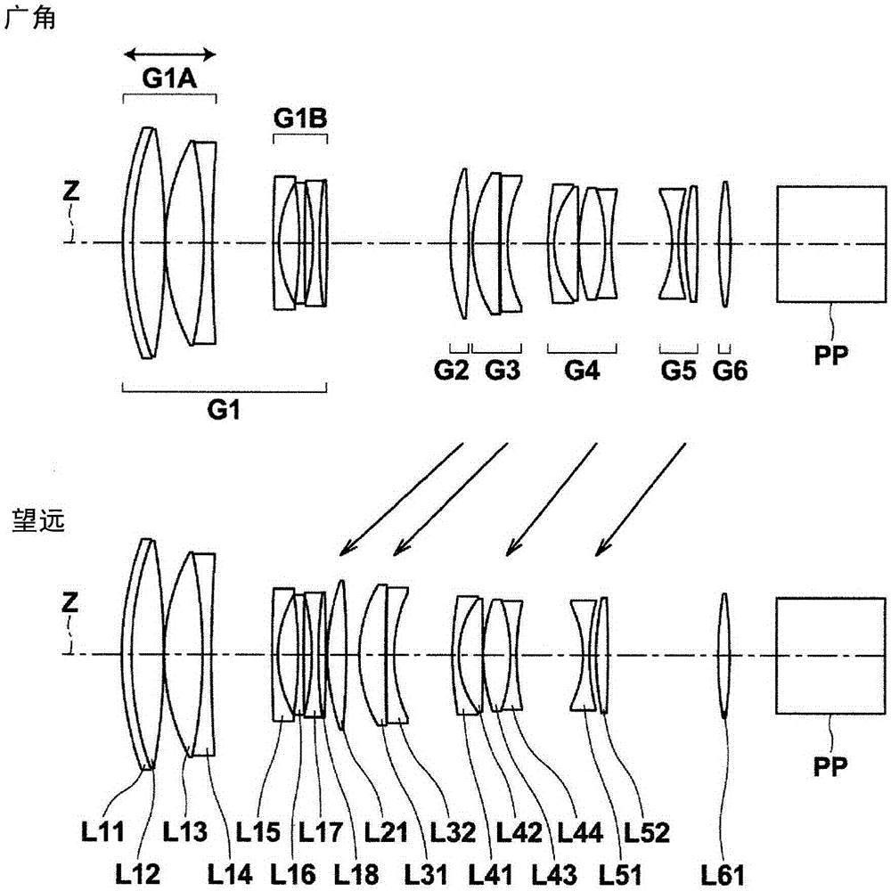
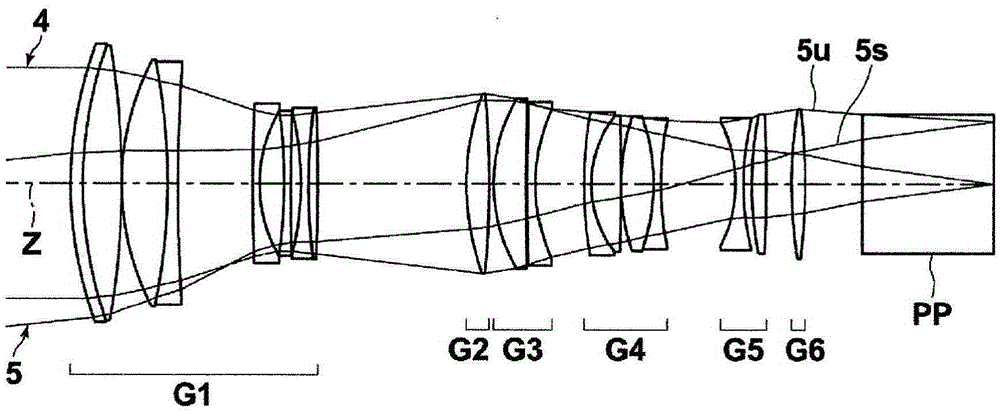
[0100] The structural diagram of the zoom lens of embodiment 1 is as figure 1 , figure 2 shown. The zoom lens of Example 1 has a six-group structure composed of the first lens group G1 to the sixth lens group G6. The first lens group G1 has negative refractive power as a whole, and is composed of a front group G1A and a rear group G1B. The front group G1A is composed of lenses L11 to L14. The rear group G1B is composed of lenses L15 to L18. The second lens group G2 is composed of only the lens L21. The third lens group G3 is composed of lenses L31 to L32. The fourth lens group G4 is composed of lenses L41 to L44. The fifth lens group G5 is composed of lenses L51 to L52. The sixth lens group G6 is composed of only the lens L61. Focusing is performed by moving only the front group G1A in the optical axis direction.
[0101] Table 1 and Table 2 respectively show the basic lens data and the value of the variable surface interval of the zoom lens of Example 1. In the Si ...
Embodiment 2
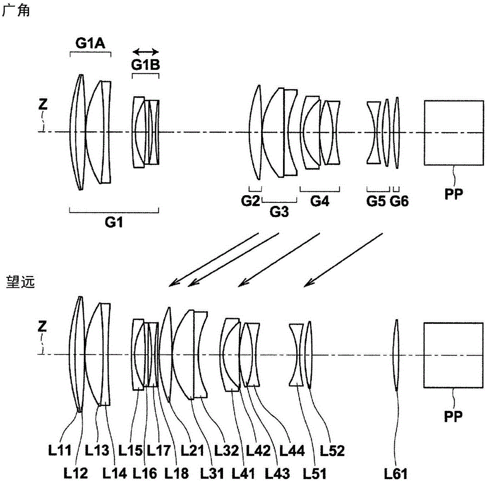
[0115] image 3 A lens configuration diagram showing the zoom lens of Example 2, Figure 4 The optical path diagram at the wide-angle end is shown. The zoom lens of Example 2 has a six-group structure composed of the first lens group G1 to the sixth lens group G6. The first lens group G1 has negative refractive power as a whole, and is composed of a front group G1A and a rear group G1B. The front group G1A is composed of lenses L11 to L14. The rear group G1B is composed of lenses L15 to L18. The second lens group G2 is composed of only the lens L21. The third lens group G3 is composed of lenses L31 to L32. The fourth lens group G4 is composed of lenses L41 to L44. The fifth lens group G5 is composed of lenses L51 to L52. The sixth lens group G6 is composed of only the lens L61. Focusing is performed by moving only the rear group G1B in the optical axis direction.
[0116] Table 3 and Table 4 respectively show the basic lens data and the value of the variable surface i...
Embodiment 3
[0125] Figure 5 A lens configuration diagram showing the zoom lens of Example 3, Figure 6 The optical path diagram at the wide-angle end is shown. The zoom lens of Example 3 has a five-group structure composed of the first lens group G1 to the fifth lens group G5. The first lens group G1 has negative refractive power as a whole, and is composed of a front group G1A and a rear group G1B. The front group G1A is composed of lenses L11 to L14. The rear group G1B is composed of lenses L15 to L18. The second lens group G2 is composed of only the lens L21. The third lens group G3 is composed of lenses L31 to L32. The fourth lens group G4 is composed of lenses L41 to L46. The fifth lens group G5 is composed of only the lens L51. A floating focus method in which focusing is performed by moving the front group G1A and the rear group G1B in the optical axis direction so that the distance between the front group G1A and the rear group G1B changes.
[0126] Table 5 and Table 6 sh...
PUM
 Abstract
Description
Claims
Application Information
 - R&D
- Intellectual Property
- Life Sciences
- Materials
- Tech Scout
- Unparalleled Data Quality
- Higher Quality Content
- 60% Fewer Hallucinations
Browse by: Latest US Patents, China's latest patents, Technical Efficacy Thesaurus, Application Domain, Technology Topic, Popular Technical Reports.
© 2025 PatSnap. All rights reserved.Legal|Privacy policy|Modern Slavery Act Transparency Statement|Sitemap|About US| Contact US: help@patsnap.com


