Camera lens and camera device

A camera lens and camera device technology, applied in optical components, instruments, optics, etc., can solve the problems of increased load on the drive system, increased weight of the focusing group, etc., and achieve the goal of suppressing large diameter, small F value, and maintaining performance Effect

Active Publication Date: 2020-05-12
FUJIFILM CORP
View PDF5 Cites 0 Cited by
  • Summary
  • Abstract
  • Description
  • Claims
  • Application Information

AI Technical Summary

Problems solved by technology

[0008] However, in the floating focus optical systems described in the above-mentioned Patent Documents 1 and 2, the first lens group is a lens group having negative refractive power, and the focus group positioned subsequent to the first lens group has a large diameter. Therefore, the mirror body is also easy to become a large diameter
In addition, since the weight of the focus group with a large diameter increases, there is also a problem that the load on the drive system increases and it is difficult to increase the focus speed.

Method used


Image

  • Camera lens and camera device
  • Camera lens and camera device
  • Camera lens and camera device

Examples


Embodiment 1

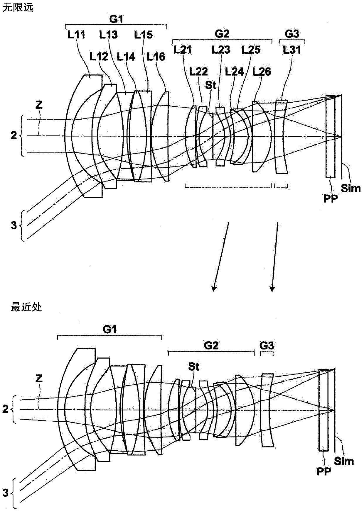
[0117] figure 1 The structure of the imaging lens of Example 1 is shown. It should be noted, figure 1 The detailed descriptions of each lens group and each lens in the structure are as above, so repeated descriptions are omitted here. Tables 1 to 3 below show numerical data showing the detailed configuration of the imaging lens of Example 1. Table 1 shows basic lens data, Table 2 shows aspheric coefficients, and Table 3 shows the values ​​of various factors and variable facet intervals.

[0118] The column of Si in Table 1 shows the numbering of the faces of the constituent elements such that the object-side face of the constituent element closest to the object side is the first and increases sequentially toward the image side. i (i=1, 2, 3, ...) surface numbers, the Ri column shows the radius of curvature of the i-th surface, and the Di column shows the i-th surface and the i+1-th surface on the optical axis The plane spacing on Z, the Ndj column shows the jth (j=1, 2, 3,...

Embodiment 2

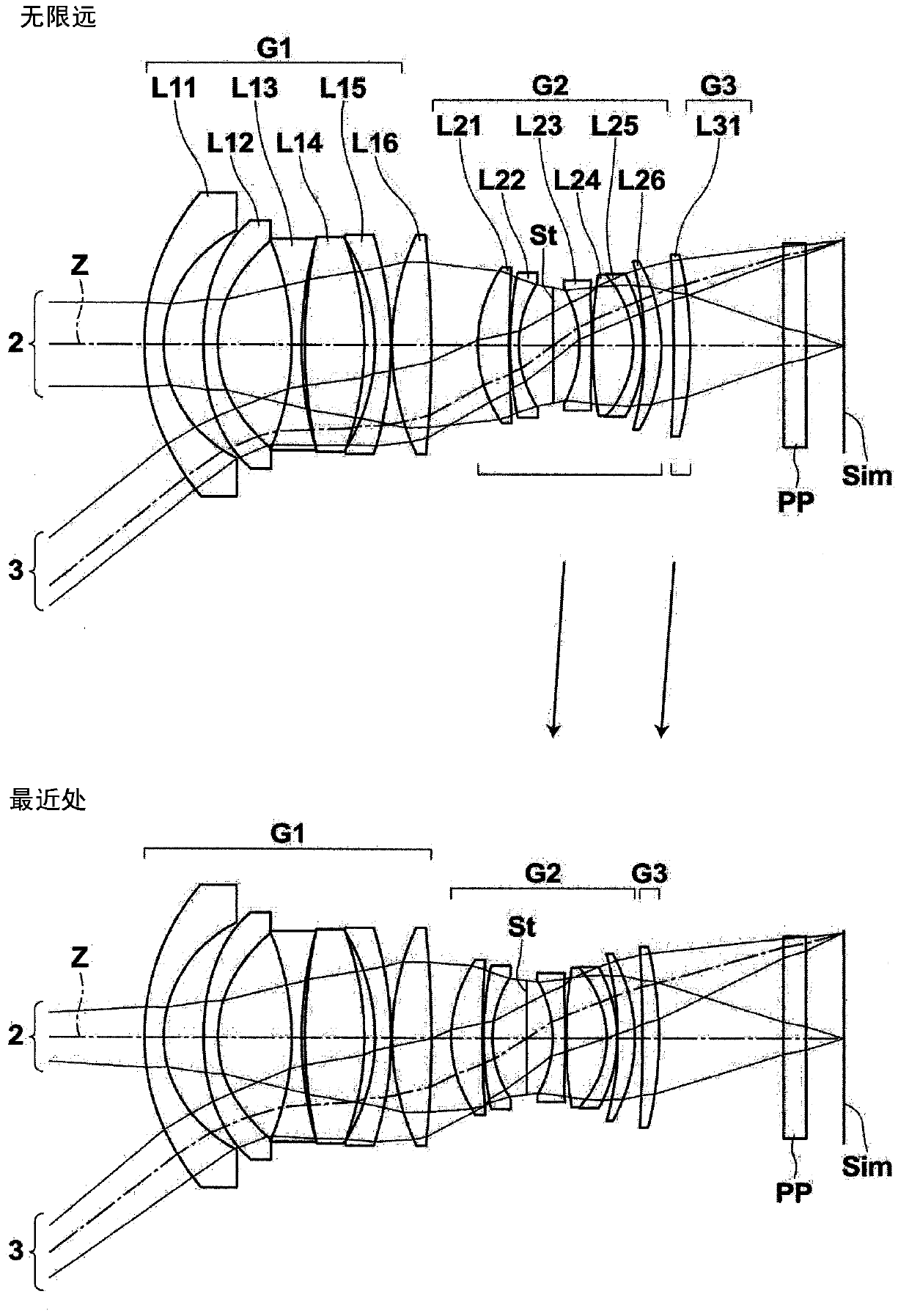
[0142] figure 2 The structure of the imaging lens of Example 2 is shown. The imaging lens of Example 2 is composed of three lens groups of the first lens group G1 to the third lens group G3. At the time of focusing, the first lens group G1 is fixed, and the second lens group G2 and the third lens group G3 are moved such that the mutual interval in the optical axis direction changes. The number of lenses each of the first lens group G1 to the third lens group G3 has is the same as that of the first embodiment. Table 4 shows basic lens data of the imaging lens of Example 2, Table 5 shows aspheric coefficients, and Table 6 shows values ​​of various factors and variable surface intervals. Image 6 Various aberration diagrams of the imaging lens of Example 2 are shown.

[0143] 【Table 4】

[0144] Example 2

[0145] Si Ri Di Ndj νdj 1 33.1597 2.4333 1.80518 25.42 2 17.4979 5.0163 *3 41.2286 1.8000 1.58313 59.38 *4 18.5501 9.271...

Embodiment 3

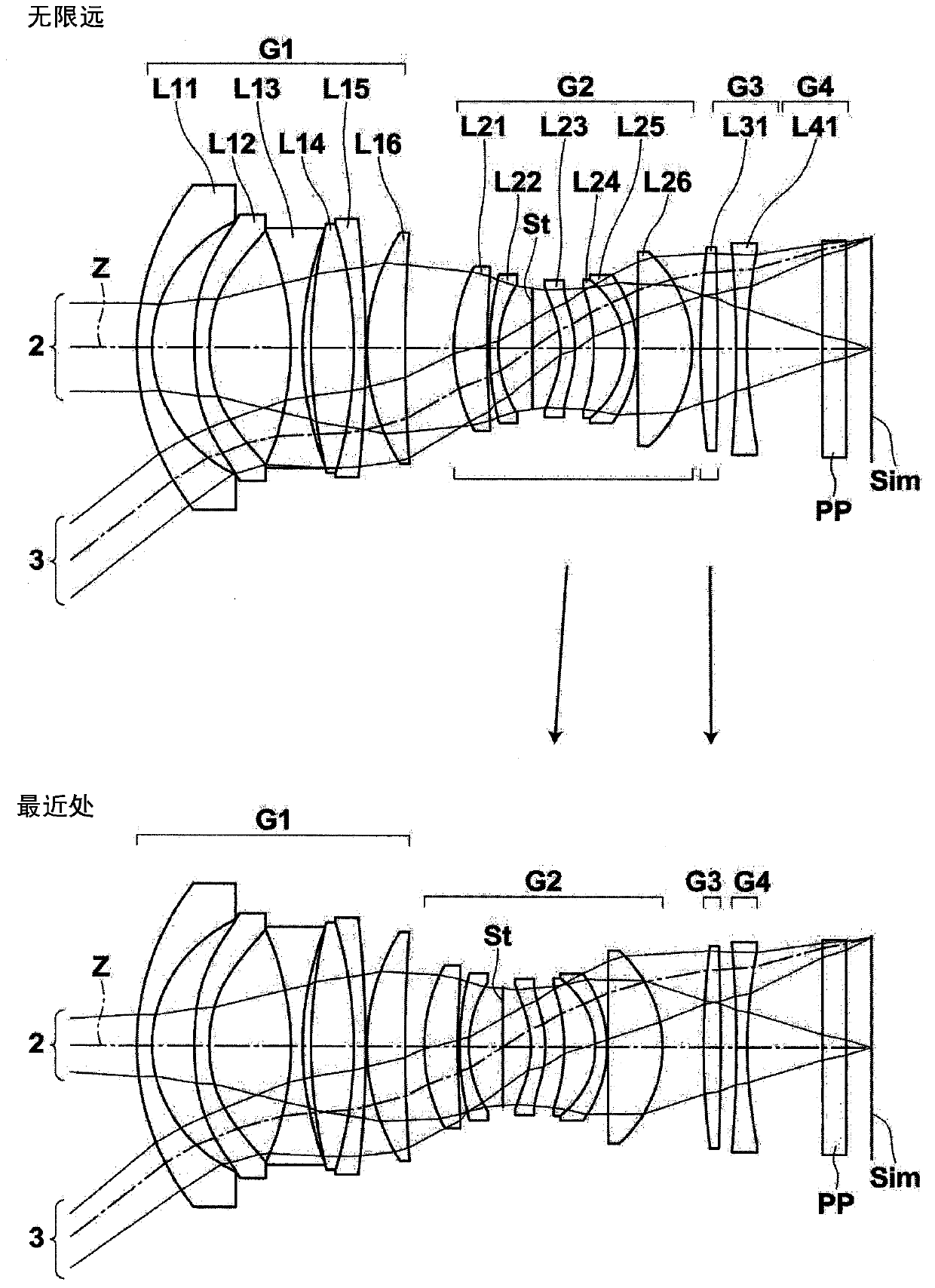
[0153] image 3 The structure of the imaging lens of Example 3 is shown. The imaging lens of Example 3 is composed of four lens groups of the first lens group G1 to the fourth lens group G4. When focusing, the first lens group G1 and the fourth lens group G4 are fixed, and the second lens group G2 and the third lens group G3 are moved such that the mutual interval in the optical axis direction changes. The fourth lens group G4 is composed of only the lens L41. The number of lenses each of the first lens group G1 to the third lens group G3 has is the same as that of the first embodiment. Table 7 shows basic lens data of the imaging lens of Example 3, Table 8 shows aspherical coefficients, and Table 9 shows values ​​of various factors and variable surface intervals. Figure 7 Various aberration diagrams of the imaging lens of Example 3 are shown.

[0154] 【Table 7】

[0155] Example 3

[0156] Si Ri Di Ndj νdj 1 35.7060 1.8000 1.92119 23.96 2 ...


PUM


Abstract

An imaging lens includes, consecutively in order from the most object-side, a positive first lens group, a positive second lens group and a third lens group. Focusing on an object at close distance from a state of having focused on an object at infinity is performed by moving the second lens group and the third lens group in such a manner that a distance between the second lens group and the third lens group changes while the first lens group is fixed. The first lens group includes, consecutively in order from the most object-side, a negative first lens and a negative second lens.

Description

technical field [0001] The present invention relates to an imaging lens and an imaging device, and particularly relates to an imaging lens suitable for a digital camera, a video camera, and the like, and an imaging device including such an imaging lens. Background technique [0002] Conventionally, as an imaging lens used in an imaging device such as a digital camera, a floating focus type lens system in which focusing is performed by moving two or more lens groups on mutually different trajectories has been proposed. For example, in the following patent documents 1 and 2, there are described optical systems in which a first lens group that is fixed when focusing is arranged on the most object side, and two lens groups that are closer to the image side than the first lens group are arranged. These two lens groups are moved such that the distance between the two lens groups changes during focusing. [0003] prior art literature [0004] patent documents [0005] Patent Doc...

Claims


Application Information

Patent Timeline
Patent Type & Authority Patents(China)
IPC IPC(8): G02B13/06G02B13/00G02B13/18
CPCG02B13/0035G02B13/06G02B13/18G02B13/04
Inventor 齐藤广树铃木隆
Owner FUJIFILM CORP
Why Eureka
Try Eureka