Fuel supply device

A fuel supply device and fuel technology, which is applied to the arrangement combined with the fuel supply of an internal combustion engine, a liquid fuel feeder, a power plant, etc. The effect of increasing the diameter and ensuring durability

Active Publication Date: 2016-11-09
HITACHI ASTEMO LTD
View PDF5 Cites 1 Cited by
  • Summary
  • Abstract
  • Description
  • Claims
  • Application Information

AI Technical Summary

Problems solved by technology

In such a fuel supply device in which the pump holding wall and the second casing are connected by a snap-fit ​​mechanism so that the first casing and the second casing are combined with each other, the device's friction caused by the snap-fit ​​mechanism is suppressed. It is effective to increase the diameter, but in the structure disclosed above, there is a disadvantage that since the end portion of the elastic piece is close to the mounting flange, when the elastic piece is bent outward in the radial direction to release the buckle In the engaged state of the fixing mechanism, the mounting flange becomes an obstacle, and the release operation becomes difficult

Method used


Image

  • Fuel supply device
  • Fuel supply device
  • Fuel supply device

Examples


no. 1 Embodiment approach

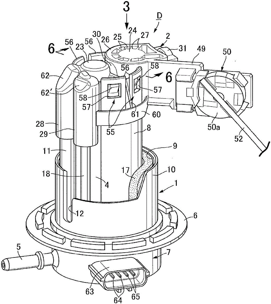
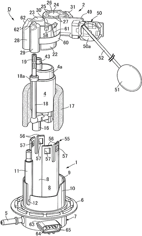
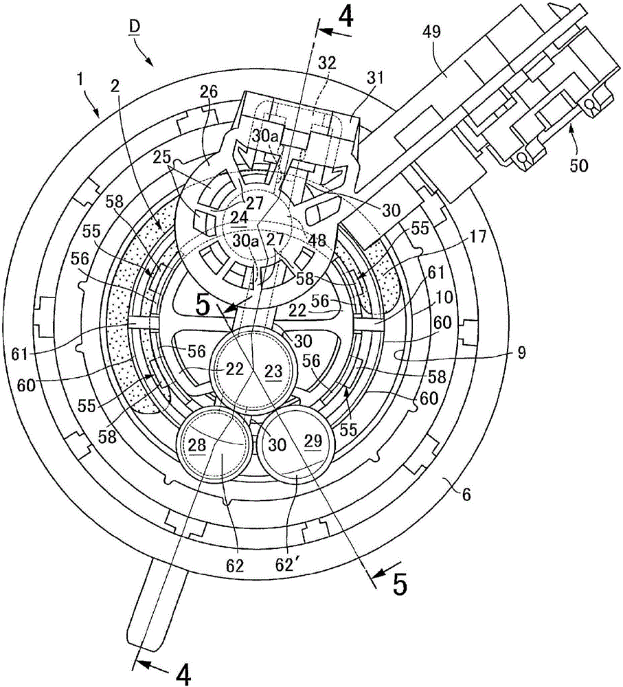
[0028] first, Figure 1 to Figure 6 Among them, on the floor Ta of the fuel tank T mounted on the vehicle (refer to Figure 4 ) is mounted with a fuel supply device D of the present invention that supplies fuel in the fuel tank T to a fuel injection valve (not shown) of the engine.

[0029] This fuel supply device D is composed of the following parts: a first casing 1 made of synthetic resin mounted on the bottom plate Ta of the fuel tank T; a second housing 2 ; and a fuel pump 4 held between the two housings 1 , 2 .

[0030] The first casing 1 is integrally formed with a bottomed cylindrical base portion 7, a fuel take-out pipe 5 is provided at the lower portion of the base portion 7, and an opening portion attached to the bottom plate Ta of the fuel tank T is provided at the upper portion. Mounting flange 6 around Tb, the base portion 7 closing the above-mentioned opening portion Tb; a pair of pump holding walls 8, which stand up from the bottom of the base portion 7; *sur...


PUM


Abstract

Provided is a fuel supply device in which a fuel pump (4) is held by the pump holding wall (8) of a first housing (1) and the fitted wall (22) of a second housing (2) and the pump holding wall (8), and the fitted wall (22) are connected via a snap-fit mechanism (55). The snap-fit mechanism (55) is configured from: an elastic piece (56) that fits the fitted wall (22) to the inner periphery of the pump holding wall (8) and that extends from the tip of the pump holding wall (8) and comes into contact with the outer surface of the fitted wall (22); a locking hole (57) that is provided to the tip section of the elastic piece (56); and a locking claw (58) that is provided so as to protrude from the outer surface of the fitted wall (22) and that engages with the locking hole (57) as a result of the elastic force of the elastic piece (56). A regulating wall (60) that regulates bending of the elastic piece (56) in the radially outward direction is provided to the second housing (2). As a result, it is possible to provide a fuel supply device in which the engaged state of a snap-fit mechanism can be easily released without interference from an attachment flange.

Description

technical field [0001] The present invention mainly relates to a fuel supply device for supplying fuel to a fuel injection valve of an engine, and more particularly to an improvement of the fuel supply device. The first housing has a base portion having a fuel take-out pipe at one end and a mounting flange attached to the fuel tank at the other end, and a pump holding wall, the base portion closing an opening of the fuel tank , the pump holding wall extends into the fuel tank from the base portion, the second housing cooperates with the pump holding wall to hold the fuel pump and has a fuel pipe for guiding the discharged fuel of the fuel pump to The fuel take-out tube. Background technique [0002] The fuel supply device described above is known as disclosed in Patent Document 1. [0003] prior art literature [0004] patent documents [0005] Patent Document 1: Japanese Patent Laid-Open No. 2008-82263 Contents of the invention [0006] The problem to be solved by th...

Claims


Application Information

Patent Timeline
Patent Type & Authority Applications(China)
IPC IPC(8): F02M37/10F02M37/00F02M37/44F02M37/50
CPCB60K2015/03217F02M37/0029F02M37/103B60K2015/03243F02M37/50F02M37/44
Inventor 内藤敏彦
Owner HITACHI ASTEMO LTD
Why Eureka
Try Eureka