Internal combustion engine stop control device

A technology of stop control and internal combustion engine, applied in the direction of engine control, internal combustion piston engine, combustion engine, etc., can solve the problem of engine output torque drop, etc., and achieve the effect of preventing the vehicle from starting and reducing discomfort.

Inactive Publication Date: 2016-06-08
SUZUKI MOTOR CORP
View PDF5 Cites 0 Cited by
  • Summary
  • Abstract
  • Description
  • Claims
  • Application Information

AI Technical Summary

Problems solved by technology

[0004] As a result, the output torque of the engine will drop rapidly

Method used


Image

  • Internal combustion engine stop control device
  • Internal combustion engine stop control device
  • Internal combustion engine stop control device

Examples


Embodiment Construction

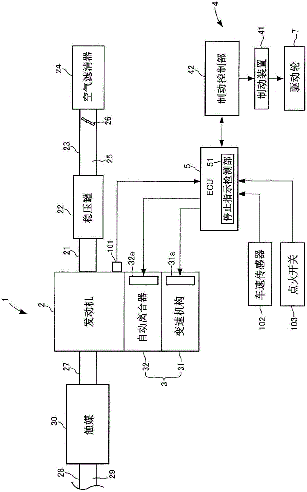
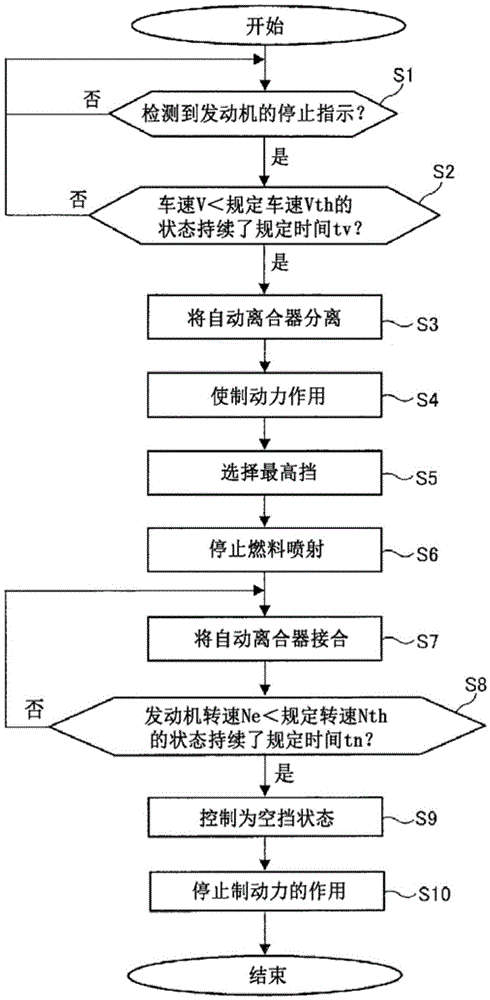
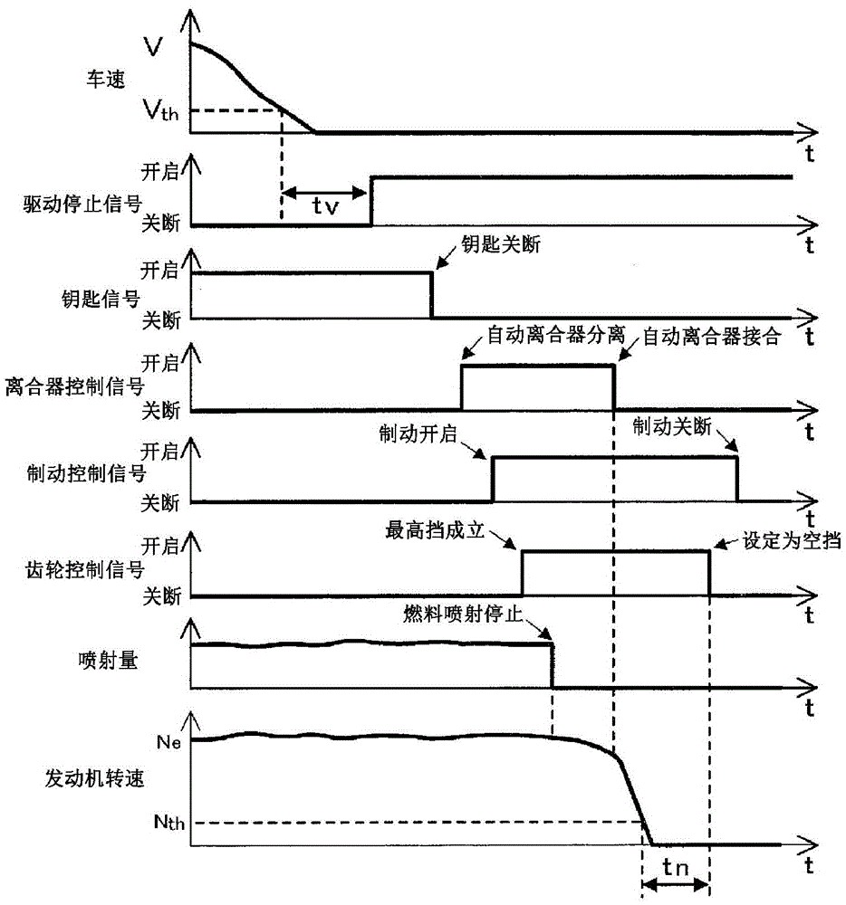
[0024] Hereinafter, embodiments of the present invention will be described in detail with reference to the drawings. like figure 1 As shown, a vehicle 1 equipped with an internal combustion engine stop control device according to an embodiment of the present invention includes an engine 2 as an internal combustion engine, an AMT (Automated Manual Transmission: automatic manual transmission) 3, a braking system 4, and an ECU (Electric Control Unit) as a control unit. : electronic control unit) 5 and drive wheel 7. In addition, in figure 1 In the figure, only one drive wheel 7 among a pair of drive wheels 7 is shown in figure.

[0025] The engine 2 is a four-stroke gasoline engine that generates driving force for the vehicle 1 by performing a series of four strokes including an intake stroke, a compression stroke, an expansion stroke, and an exhaust stroke and performing ignition between the compression stroke and the expansion stroke. constituted.

[0026] An intake manif...


PUM


Abstract

An internal combustion engine stop control device capable of reducing passenger discomfort related to vibration generated by an internal combustion engine when the internal combustion engine stops. The internal combustion engine stop control device is mounted in a vehicle comprising an engine and an AMT that automatically performs shift and clutch operations. The internal combustion engine stop control device performs a shift operation that switches the gear position to the highest position and a clutch operation that switches an automatic clutch to a transmission state, on the condition that said device has detected that the vehicle speed (V) is less than a prescribed vehicle speed (Vth) and an engine stop instruction has been given.

Description

technical field [0001] The present invention relates to an internal combustion engine stop control device, and more particularly, to an internal combustion engine stop control device used in a vehicle equipped with an automatic clutch and an automatic shift automatic transmission, so-called AMT (Automated Manual Transmission: Automatic Manual Transmission). Background technique [0002] In a vehicle equipped with an engine as an internal combustion engine, it is known that vibration generated by the engine when the engine is stopped is transmitted to the vehicle body and is transmitted to the occupants as uncomfortable vibration. In particular, such vibration at the time of engine stop becomes prominent in the resonance rotational speed region in the process of decreasing the engine rotational speed. Consistent and resonant rotational speed region. [0003] Conventionally, a device described in Japanese Patent No. 3991674 (Patent Document 1) is known as an engine stop contr...

Claims


Application Information

Patent Timeline
Patent Type & Authority Applications(China)
IPC IPC(8): B60W10/00B60W10/02B60W10/04B60W10/06B60W10/10B60W10/11F02D29/00F02D29/02F16H59/34F16H59/44F16H61/02F16H61/68
CPCB60W10/02B60W10/06B60W10/10B60W10/11B60W10/18B60W2520/10B60W2710/021B60W2710/06B60W2710/1005F02D17/00F02D29/02F16H59/34F16H59/44F16H59/50F16H61/0204F16H2312/20Y02T10/40
Inventor 汤山亮
Owner SUZUKI MOTOR CORP
Why Eureka
Try Eureka