Temperature compensation method of magnetic control fields in a hall sensor with OS adaption

A technology of temperature compensation and displacement sensor, applied in the field of displacement sensor

Active Publication Date: 2016-06-22
TE CONNECTIVITY GERMANY GMBH
View PDF9 Cites 12 Cited by
  • Summary
  • Abstract
  • Description
  • Claims
  • Application Information

AI Technical Summary

Problems solved by technology

[0016] However, the existing 2D and 3D Hall sensors and measurement methods described above have the disadvantage that they react in a very sensitive manner to variations in the spacing between the control magnet and the Hall sensor
[0021] However, using the evaluation method with OS adaptation can lead to a negative influence on the temperature behavior of the arctangent calculation by controlling the magnetic field of the magnet
Although the values ​​of the detected magne

Method used


Image

  • Temperature compensation method of magnetic control fields in a hall sensor with OS adaption
  • Temperature compensation method of magnetic control fields in a hall sensor with OS adaption
  • Temperature compensation method of magnetic control fields in a hall sensor with OS adaption

Examples


Embodiment Construction

[0034] Originally referenced below figure 1 7 will explain the present invention in more detail. For the sake of simplicity, the magnetic flux density will only be referred to as the magnetic field below.

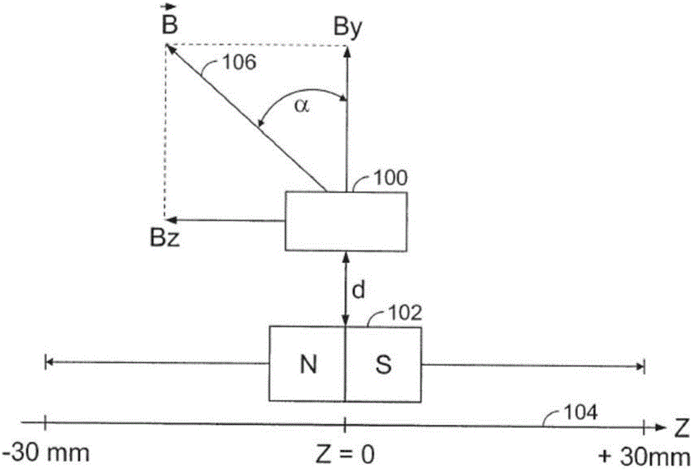
[0035] figure 1 A displacement sensor configuration according to the invention is shown in . A magnetic field sensor (eg, 3D Hall sensor 100 ) is mounted to be fixed in position, whereas permanent magnet 102 is configured to move linearly relative to Hall sensor 100 . The permanent magnet 102 has such poles that its north / south axis is oriented parallel to the direction of movement 104 . In principle, however, the principles of the invention can also be applied to configurations in which the permanent magnet 102 has such poles that its north / south axis extends transversely with respect to the direction of movement. Can make the permanent magnet 102 self- figure 1 The zero position displacement shown in is (for example) about 30mm. The Hall sensor 100 detects at least ...


PUM


Abstract

The present invention relates to a measurement method for detecting a relative position of a magnetic field source in relation to a magnetic field sensor. At least two magnetic field components of the produced magnetic field are detected by means of the magnetic field sensor. The present invention further also relates to a corresponding displacement sensor. According to the present invention, an output signal which corresponds to the position of the magnetic field source relative to the magnetic field sensor is established, based on a quotient of the detected magnetic field components and an offset correction, wherein the effect of the temperature on the produced magnetic field is compensated for before the output signal is established.

Description

technical field [0001] The invention relates to a measurement method for detecting the relative position of a magnetic field source with respect to a magnetic field sensor. At least two magnetic field components of the magnetic field are detected by the magnetic field sensor. The invention further relates to a corresponding displacement sensor. Background technique [0002] By means of the method according to the invention it is in particular aimed at compensating the thermally induced variation effect of the Hall effect-based magnetic control field on the output signal of the magnetic sensor, from both detected magnetic field components and offset slope adaptation (OS adaptation) The quotient of establishes the output signal. [0003] The measuring principle of a three-dimensional (3D) Hall sensor is based on establishing the components of the magnetic flux density vector B in three spatial directions. as in figure 1 As shown in , a magnetic field source 102 (eg, a perm...

Claims


Application Information

Patent Timeline
IPC IPC(8): G01R33/00G01R33/07G01D5/14
CPCG01D5/145G01R33/0082G01R33/07G01D3/036G01R15/202
Inventor O.沙夫
Owner TE CONNECTIVITY GERMANY GMBH
Why Eureka
Try Eureka