Alternating current charging pile function testing device
A technology for AC charging piles and functional testing, which is applied to measuring devices, measuring electricity, and measuring electrical variables, etc. It can solve the problems of lack of charging pile detection devices, human errors, and no testing functions.
Inactive Publication Date: 2016-07-06
常胜 +2
View PDF8 Cites 15 Cited by
- Summary
- Abstract
- Description
- Claims
- Application Information
AI Technical Summary
Problems solved by technology
The national standard GB/T18487.1-2015 for the conductive charging system of electric vehicles has been officially implemented on January 1, 2016. The charging piles in the future must meet this standard, but there is no testing instrument that meets this standard on the market. Charging piles Manufacturers still rely on general-purpose instrum
Method used
View moreImage
Smart ImageViewing Examples
Examples
 PUM
 Abstract
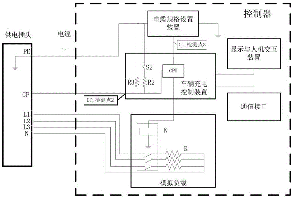
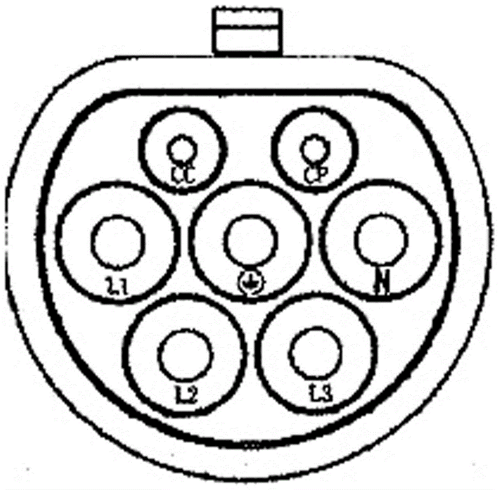
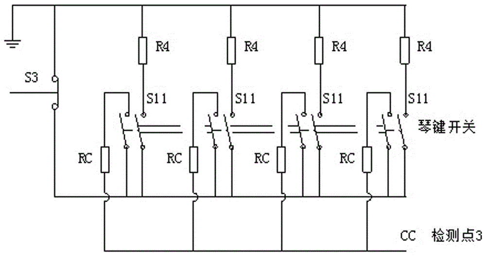
The invention solves the test of control guiding functions between an alternating current charging pile and an electric car charging control device specified in the GB/T 18487.1-2015 and the electric car charging load simulation, and in particular relates to an alternating current charging pile function testing device, which comprises a power supply plug, a cable and a controller. The controller comprises a car charging control device, a cable specification setting device, a display and man-machine interaction device, a communication interface and a simulated load. The controller is provided with a plurality of detection points. The power supply plug is connected with the controller through the cable. The car charging control device includes four output ports which are connected with the cable specification setting device, the display and man-machine interaction device, the communication interface and the simulated load. The alternating current charging pile function testing device provides a tool for effective detection and estimation of the correction and reliability of the alternating current charging pile control guiding and charging functions for special testing mechanisms or alternating current/direct current charging pile production enterprises, and will greatly promotes the technology development and technology progress of the industry.
Description
technical field [0001] The invention is used to solve the test of the control and guidance function between the AC charging pile and the electric vehicle charging control device specified in GB / T18487.1-2015 and the simulation of the charging load of the electric vehicle, and specifically relates to an AC charging pile function test device . Background technique [0002] The electric vehicle AC charging pile intelligent detection device is a detection device for electric vehicle charging facilities. Generally speaking, the device simulates the interface function of electric vehicles to detect the interface and charging sequence function of the AC charging pile; through the connection with the AC charging pile Communication can detect the frequency, duty cycle, and amplitude of the PWM signal sent by the charging pile, and at the same time control the load box to overload the charging current according to the maximum output current capacity represented by the duty cycle, to d...
Claims
Login to View More Application Information
Patent Timeline
 IPC IPC(8): G01R31/00
CPCG01R31/00
Inventor 常胜马军周刘忠菁
Owner 常胜
Features
- R&D
- Intellectual Property
- Life Sciences
- Materials
- Tech Scout
- Unparalleled Data Quality
- Higher Quality Content
- 60% Fewer Hallucinations
Learn More Browse by: Latest US Patents, China's latest patents, Technical Efficacy Thesaurus, Application Domain, Technology Topic, Popular Technical Reports.
© 2025 PatSnap. All rights reserved.Legal|Privacy policy|Modern Slavery Act Transparency Statement|Sitemap|About US| Contact US: help@patsnap.com


