Automobile torsion beam back bridge fatigue test device

A kind of fatigue test and torsion beam technology, applied in the direction of vehicle suspension/shock absorber testing, etc., can solve the problems of experimental error, failure to detect fatigue cracking of rear axle in time, and high cost, so as to avoid human judgment errors and shorten fatigue experiments. The effect of simple cycle and device structure

Active Publication Date: 2017-03-22
NINGBO JIANXIN CHASSIS SYST
View PDF11 Cites 2 Cited by
  • Summary
  • Abstract
  • Description
  • Claims
  • Application Information

AI Technical Summary

Problems solved by technology

However, the real vehicle road test costs are high, the cycle is long, and the coordination of other resources is required; in laboratory experiments, hydraulic cylinders are often used to drive the rear axle to complete the experiment, but the loading frequency of the hydraulic cylinder in this experiment is low (usually 1Hz-2Hz), The te

Method used


Image

  • Automobile torsion beam back bridge fatigue test device

Examples


Embodiment Construction

[0013] The present invention will be further described in detail below in conjunction with the accompanying drawings and embodiments.

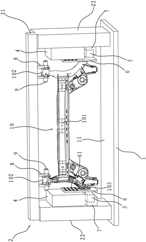
[0014] like figure 1 Shown, a kind of automobile torsion beam type rear axle fatigue test device, comprises workbench 1, and the table top 11 of this workbench 1 is provided with stand 2, and this stand 2 is door shape, comprises the beam 21 on the top and is arranged on The vertical beams 22 on both sides of the cross beam 21 . The torsion beam rear axle 10 of the automobile to be tested is hinged on the stand 2. Specifically, two hinged supports 8 are arranged on the crossbeam 21, and a rotating shaft is respectively pierced on each bush sleeve 102 of the torsion beam rear axle 10. 9, and the two ends of the rotating shaft 9 are respectively connected with the two ends of the hinged support 8, so that the bush sleeve 102 forms a hinge with the stand 2, and at the same time the torsion beam 101 of the torsion beam rear axle 10 of the automob...


PUM


Abstract

The invention relates to an automobile torsion beam back bridge fatigue test device which comprises a worktable and a vertical frame. A back bridge to be tested is hinged to the vertical frame through two bushing casings. The device also comprises two electromagnetic driving components, and each of the electromagnetic driving components comprises an electromagnet and a driving steel plate. Each driving steel plate is fixed to the corresponding flange plate on the back bridge to be tested, the electromagnets at two sides can alternately apply opposite acting force to the corresponding driving steel plates, and thus the corresponding flange plates have relative displacement. The device also comprises displacement sensors arranged at two sides of the back bridge to be tested, and each of the displacement sensors is used for measuring the relative displacement of the corresponding flange plate. The structure of the automobile torsion beam back bridge fatigue test device is simple, the electromagnets are used to load a load, the back bridge fatigue test cycle can be greatly shortened, and at the same time, when the back bridge has fatigue cracking, the vibration frequency is reduced. According to the device, the displacement sensors are used to scan the vibration frequency of the back bridge, thus whether the back bridge has the fatigue cracking can be automatically judged, and the errors of artificial judgment are avoided.

Description

technical field [0001] The invention relates to the field of auto parts test devices, in particular to an automobile torsion beam type rear axle fatigue test device. Background technique [0002] The torsion beam rear axle of the automobile is hinged on the vehicle body, which can slow down the impact between the rear wheel and the ground, reduce noise, and improve the comfort and stability of the vehicle. The torsion beam rear axle of an automobile generally includes a torsion beam and trailing arms connected to both ends of the torsion beam, wherein a spring tray is fixed at the connection between each trailing arm and the torsion beam, and a bushing is fixed at one end of each trailing arm tube, and the other end is fixed with a flange plate. The Chinese utility model patent whose patent number is ZL201120271981.5 (the authorization announcement number is CN202163272 U), the Chinese invention patent whose application number is 201510132767.4 (the application publication ...

Claims


Application Information

Patent Timeline
IPC IPC(8): G01M17/04
CPCG01M17/04
Inventor 范华祥徐凯立刘佳良薛仁杰叶雪萍
Owner NINGBO JIANXIN CHASSIS SYST
Why Eureka
Try Eureka