

Lighting fire nozzle
A water gun and firefighting technology, applied in the fields of electronic circuits and mechanical structures, can solve the problems of increasing the danger of firefighters' rescue, insufficient lighting in buildings, and inconvenient rescue.
Inactive Publication Date: 2016-07-13
孔国琴
View PDF0 Cites 0 Cited by
- Summary
- Abstract
- Description
- Claims
- Application Information
AI Technical Summary
Problems solved by technology
[0002] In fire rescue, when a fire breaks out at night, the internal lighting of the building is seriously insufficient, causing firefighters to hold flashlights for rescue, which is not only inconvenient and rescue, but also increases the danger of firefighters' rescue
Method used
View moreImage
Smart ImageViewing Examples

Examples
Embodiment Construction
[0008] The present invention will be further described below in conjunction with the accompanying drawings.
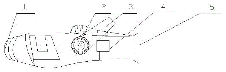
[0009] Such as figure 1 As shown, it is composed of LED strong aperture (1), water pressure gauge (2), lift bar (3), water flow power generation device (4), and water pipe interface (5). When in use, the water pipe interface (5) is connected to the high-pressure water pipe, and the high-pressure water flow is used for power generation by the water flow power generation device (4), and the electric energy is used for the LED strong aperture (1) to emit light, and the lifting bar (3) is convenient for the user Lifting to improve rescue efficiency.
Login to View More PUM
 Abstract
The invention discloses a lighting fire nozzle. The lighting fire nozzle comprises an LED high-light aperture, a water pressure gauge, a lifting bar, a water-current power generating device and a water tube port. The lighting fire nozzle is characterized in that the LED high-light aperture is arranged at the front end of a port of the fire nozzle and used for emitting light; the water pressure gauge is used for displaying the current water pressure numerical value; the lifting bar is integrally connected with a casing of the water pressure gauge and used for facilitating lifting of the fire nozzle for a user; the water-current power generating device is arranged in the fire nozzle, and is used for generating power with water currents when high-pressure water currents pass through and providing power for the LED high-light aperture; the water tube port is formed in the tail end of the fire nozzle and used for being connected with a high-pressure water tube.
Description
technical field [0001] The invention relates to the technical field of mechanical structures and the field of electronic circuits, in particular to a self-illuminating fire water gun. Background technique [0002] In fire rescue, when a fire breaks out at night, the internal lighting of the building is seriously insufficient, causing firefighters to carry out rescue with a flashlight, which is not only inconvenient and rescue, but also increases the danger of firefighters' rescue. Therefore, it is necessary to design a lighting device on the fire nozzle to improve the rescue efficiency and the safety of the rescue. Contents of the invention [0003] In order to overcome the above-mentioned deficiencies in the prior art, the present invention adopts novel materials, designs a more scientific man-machine relationship, and increases the lighting function of the fire water gun. [0004] The invention discloses an illuminated fire-fighting water gun, which is composed of an LE...
Claims
Login to View More Application Information
Patent Timeline
 IPC IPC(8): A62C31/00F21L13/02F21V33/00F21Y115/10
CPCA62C31/00F21L13/02F21V33/00
Inventor孔国琴
Owner孔国琴