
Magnetron using combined cold cathode head and production method of cold cathode body

A cold cathode and magnetron technology, applied in the direction of magnetron, transit time electron tube, etc., can solve the problems of magnetron vacuum degree drop, small emission current, high voltage ceramic deformation, etc., to achieve electromagnetic compatibility performance Good, single production process, high reliability

Inactive Publication Date: 2018-01-12
UNIV OF ELECTRONICS SCI & TECH OF CHINA
View PDF7 Cites 0 Cited by
  • Summary
  • Abstract
  • Description
  • Claims
  • Application Information

AI Technical Summary

Problems solved by technology

When this type of traditional magnetron works normally, it needs to provide a certain current to the filament. The cathode needs to be heated with a power of about 40W between the center support and the upper electrode power connecting rod and the side support and the upper electrode power connecting rod. When the temperature rises to 800-1000°C, electrons are emitted, and the electrons bombard the cathode under the action of a magnetic field and raise its temperature to about 1800°C; working at such a high temperature will bring a series of problems, such as When the traditional magnetron is working, especially when it is intermittently working, it is repeatedly subjected to the influence of uneven stress such as expansion at high temperature and contraction at cooling, which will deform the high-voltage ceramics that are sealed and connected to the power connecting rod, seriously affecting the connection between the power connecting rod and the power supply. The tightness between the high-voltage ceramics reduces the vacuum degree of the magnetron, which in turn affects the performance and life of the magnetron; The electrons inside the body use additional energy to make some electrons escape across the surface barrier of the emitter to generate secondary harmonics and electromagnetic noise, which seriously affects the performance of the magnetron.
[0004] In the article "Film Field Emission Cold Cathode" (see "Optoelectronics Technology" No. 04, 1989, author: Chen Lifang et al.), a micro-electron source using a three-sandwich structure cold cathode is reported, which has room temperature work and no cathode work. consumption, no warm-up delay, etc., but it uses a planar emission structure, which needs to add a gate, and the emission current is small, so it cannot provide secondary electron emission; while the application number is CN201510675065.0, and the invention name is "A Kind of The carbon nanotube cold cathode disclosed in the patent document "Microwave Modulation Cold Cathode Micro-array Radiation Source and Its Realization Method" also adopts a planar emission structure, which cannot provide secondary electron emission and is not suitable for application in magnetrons; "Development of Ku-band Cold Cathode Magnetron" (see: Chinese Institute of Electronics Vacuum Electronics Branch - Fourteenth Annual Meeting, 2004, TN123, author: Zhou Caiyu et al.) discloses a method using cold cathode magnetron Provide primary electron emission, and use the primary electrons to bombard the surface of the secondary emitter to generate secondary electrons, but because it uses an alloy cathode structure, the ability of the primary electrons provided by the micro-tip field emission on the surface of the alloy cathode is insufficient, and the large pulse The transmission output power is only about 50kW, which is only suitable for use in medium and small tubes of Ka-band, Ku-band and X-band

Method used


Image

  • Magnetron using combined cold cathode head and production method of cold cathode body
  • Magnetron using combined cold cathode head and production method of cold cathode body
  • Magnetron using combined cold cathode head and production method of cold cathode body

Examples


Embodiment 1

[0021] Embodiment 1: make the electron emitter with graphene, the cold cathode body that metal Cu powder, Zn powder are made bonding material, and adopt the magnetron of the combined type cold cathode head of this cold cathode body as example; Its cold cathode The production method of the body is:

[0022] Steps 1 and 2. Preparation and ball milling: Weigh 2 g of graphene with a thickness of 1-10 nm, 26.6 g of Cu powder with a particle size (Fisher particle size) of 30 μm, and 11.4 g of Zn powder; cm, the height is 5.5cm in the miniature ball mill (tank), the ball mill is mixed for 120 minutes to obtain the mixture; the power of the ball mill is 150W, and the diameters of the balls in the ball mill are φ1.4cm, φ0.9cm, φ0.7cm and the ratio is 2:8 Add 36g at a ratio of 2 (the ratio of ball to material is about 7:8);

[0023] Step 3. Compression molding: placing the gained mixture in a mold cavity with a diameter of φ2.9mm, and pressing it under a pressure of 40MPa into a cylind...

Embodiment 2

[0027] Embodiment 2: the present embodiment uses carbon nanotubes as the electron emitter, metal Cu powder, Zn powder, aluminum powder as the cold cathode body of the binding material, and the magnetic control of the combined cold cathode head that adopts the cold cathode body tube as an example; the production method of its cold cathode body is:

[0028] Steps 1 and 2. Material preparation and ball milling: Weigh 2g of carbon nanotubes with a length of 5um-10um and a diameter of φ30nm-50nm, 28g of Cu powder with a particle size of 30μm, 12g of Zn powder, and 99.9% industrially pure aluminum powder 8g; place parameter together in the miniature ball mill (tank) identical with embodiment 1, ball mill 120 minutes, get compound;

[0029] Step 3. Compression molding: placing the gained mixture in a mold cavity with a diameter of φ2.8mm, and pressing it under a pressure of 40MPa into a cylindrical body of (diameter × height) φ2.8mm × 10mm;

[0030] Step 4. Sintering: put each compa...

Embodiment 3

[0033] Embodiment 3: the present embodiment uses carbon nanotube and graphene mixture as electron emitter, makes the cold cathode body of binding material with metal Cu powder, Zn powder and aluminum powder, and adopts the combined cold cathode body of this cold cathode body Take the magnetron of the cathode head as an example; the production method of the cold cathode body is:

[0034] Steps 1 and 2. Material preparation and ball milling: Weigh 1.25g of carbon nanotubes with a length of 5um-10um and a diameter of φ30nm-50nm, 1.25g of graphene with a thickness of 1-10nm, and Cu powder with a particle size of 30μm , Zn powder, each 15g of aluminum powder of industrial purity 99.9%; Place parameter together in the miniature ball mill identical with embodiment 1, ball mill mixes 120 minutes, gets compound;

[0035] Step 3. Compression molding: placing the gained mixture in a mold cavity with a diameter of φ2.8mm, and pressing it under a pressure of 40MPa into a cylindrical body o...


PUM

PropertyMeasurementUnit
diameteraaaaaaaaaa
particle diameteraaaaaaaaaa
thicknessaaaaaaaaaa

Abstract

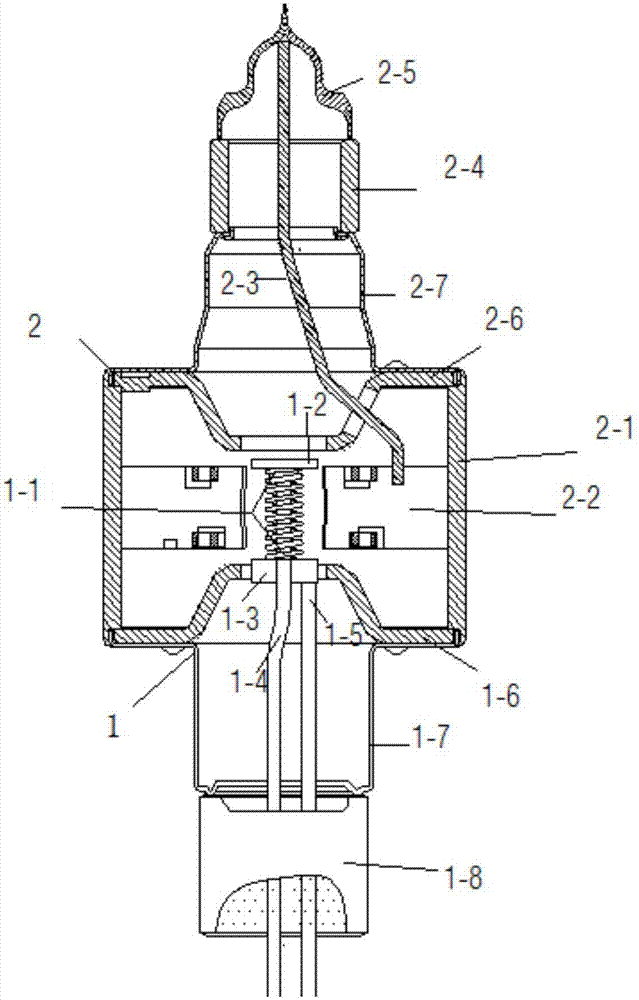
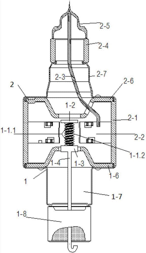
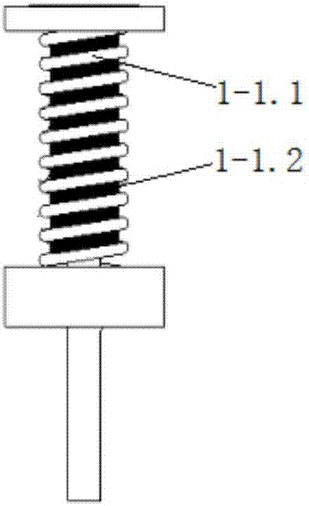
The invention is a production method of a magnetron using a combined cold cathode head and a cold cathode body in the cold cathode head. The magnetron includes upper and lower tube shells, input and output ceramic cylinders, and an exhaust pipe head. The magnetron housing including the anode cylinder and the upper and lower magnetic poles, the blades set in the anode cylinder, the upper and lower shielding caps, the combined cold cathode head composed of electrode wire and cold cathode body, and the power supply connecting rod. The production method of the cathode component, the antenna and the cold cathode body includes: material preparation and ball milling, pressing and molding, and sintering. In this invention, the filament of the traditional hot cathode is used as the electrode wire and the secondary electron emitter. Under the high voltage of the cathode and anode, the cold cathode body forms a field emission to generate primary electrons. The power supply connecting rod is connected to the lower shielding cap during operation. The temperature of some parts is lower than 500°C. Therefore, it has the characteristics of large emission flow and stable emission, high efficiency, good electromagnetic compatibility, long life, high reliability, simple and reliable production process, and low cost.

Description

technical field [0001] The invention relates to the technical field of a magnetron for microwave generation, in particular to a method for producing a magnetron using a combined cold cathode head and a cold cathode body in the cold cathode head, using the combined cold cathode head emission system The magnetron is especially suitable as a microwave source for microwave application equipment including domestic microwave ovens. Background technique [0002] Magnetron is the most widely used electronic vacuum tube. Because of its small size, high power, and convenient use, it is used as a microwave source for microwave application equipment including household microwave ovens. The cathode emission system in the magnetron structure is the heart of the whole tube. The working characteristics of the cathode have a great influence on the performance and life of the tube, so improving the working characteristics of the cathode has become an important research content; the convention...

Claims


Application Information

Patent Timeline
Patent Type & Authority Patents(China)
IPC IPC(8): H01J23/04H01J25/50
CPCH01J23/04H01J25/50
Inventor 柳建龙翟华曾葆青
Owner UNIV OF ELECTRONICS SCI & TECH OF CHINA
Learn More