True triaxial test fixture for simulating power disturbance type rock burst

A dynamic disturbance, true triaxial technology, applied in the field of rock mechanics test, can solve the problems of inability to realize dynamic disturbance type rockburst, inability to apply rigid pusher pressure loading, etc., and achieve the effect of simple structure and convenient disassembly and assembly.

Active Publication Date: 2016-08-17
GUANGXI UNIV
View PDF9 Cites 24 Cited by
  • Summary
  • Abstract
  • Description
  • Claims
  • Application Information

AI Technical Summary

Problems solved by technology

[0005] The patent with application number CN201110099596.1 introduces a true triaxial test rock sample device with a ring skeleton. This fixture is suitable for loading by hydraulic loading testing machines, but cannot be used for pressure loading by rigid push heads.
[0006] The patent with the application number CN201310178266.0 introduces a fixture device that can perform true triaxial mechanical tests. This model cannot realize the dynamic disturbance under the basic force conditions such as one-sided air, three-way five-side force, and one-way disturbance load. Simulation of type rockburst

Method used


Image

  • True triaxial test fixture for simulating power disturbance type rock burst
  • True triaxial test fixture for simulating power disturbance type rock burst
  • True triaxial test fixture for simulating power disturbance type rock burst

Examples


Embodiment 1

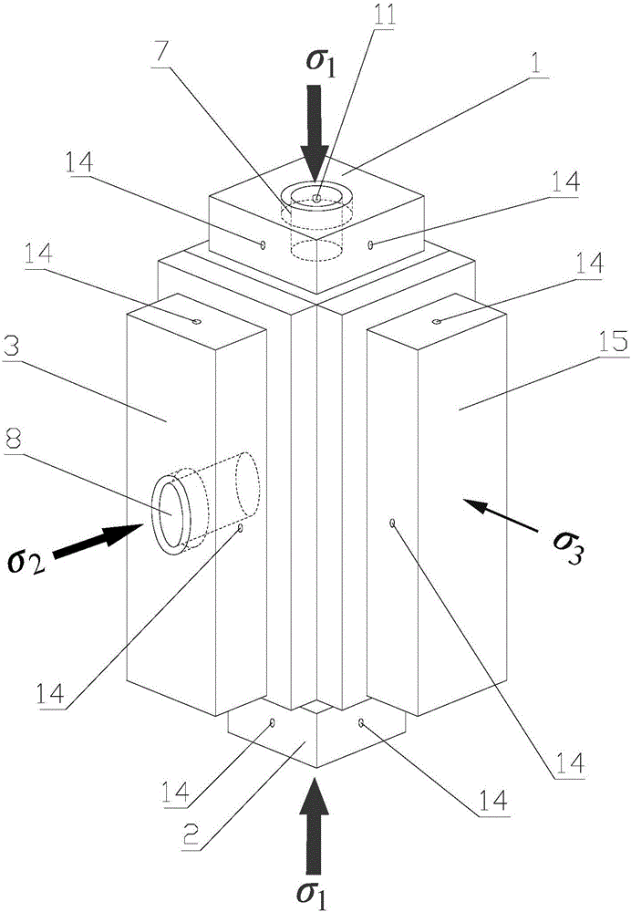
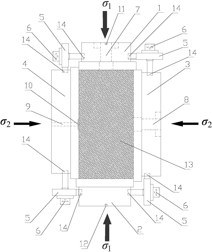
[0047] A rock sample fixture for a dynamic disturbance type true triaxial rockburst test, comprising a top pressure plate 1, a bottom pressure plate 2, a left pressure plate 4, a right pressure plate 3, a rear pressure plate 15, a horizontal disturbance rod 8, a vertical disturbance rod 7, Several common screws 6 and several U-shaped head screws 5,

[0048] A strain gauge groove 10 for placing strain gauges is opened on the contact surface between the left pressure plate 4 and the rock sample 13, and a strain gauge line through hole 9 is opened in the strain gauge groove 10,

[0049] The contact surface between the right pressure plate 3 and the rock sample 13 is provided with a horizontal disturbance rod 8 installation through hole, and the horizontal disturbance rod 8 is installed in the horizontal disturbance rod 8 installation through hole,

[0050] The contact surface between the top pressure plate 1 and the rock sample 13 is provided with a vertical disturbance rod 7 ins...

Embodiment 2

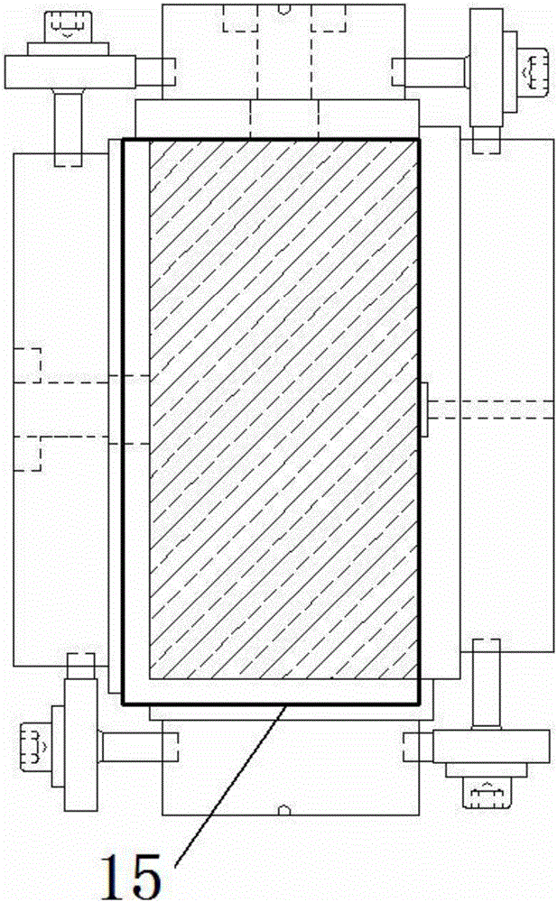
[0064] The top pressing plate 1, the bottom pressing plate 2, the left pressing plate 4, the right pressing plate 3 and the rear pressing plate 15 are respectively the top surface, the bottom surface, the left side, the right side and the rear side of the rock sample 13 in the same shape, and each side pressing plate exceeds Ninety-five percent of the area covers the corresponding surface area of ​​the rock sample (meaning that the area of ​​each side pressure plate is smaller than the corresponding surface area of ​​the rock sample and greater than ninety-five percent of the corresponding surface area of ​​the rock sample), and when installed, the top pressure plate 1 , the bottom platen 2, the left platen 4, the right platen 3 and the back platen 15 are respectively located at the center of the rock sample top surface, bottom surface, left side, right side and rear side. This is to prevent that the pressure plates on each side do not interfere with each other after the rock s...

Embodiment 3

[0068] The size of the left pressing plate 4, the right pressing plate 3 and the rear pressing plate 15 is consistent, the size of the top pressing plate 1 and the bottom pressing plate 2 are consistent, and the size of the top pressing plate 1, the bottom pressing plate 2, the left pressing plate 4, the right pressing plate 3 and the rear pressing plate 15 are larger than The size of the rock sample 13 corresponds to the top surface, bottom surface, left side, right side and rear side. During installation, the side pressure plates are combined by staggering each other to meet the movement caused by the deformation of the specimen.

[0069] The left edge and the front edge of the top pressure plate 1 are flush with the left edge and the front edge of the top surface of the rock sample 13,

[0070] The right edge and the rear edge of the bottom pressing plate 2 are flush with the right edge and the rear edge of the bottom surface of the rock sample 13,

[0071] The lower edge a...


PUM


Abstract

The invention relates to a rock sample fixture for a power disturbance type true triaxial rock burst test. A strain gage slot used for containing a strain gage is formed on a contact surface of a left pressing plate of a fixture and a rock sample; a strain gage line through hole is formed in the strain gage slot; a horizontal disturbance rod mounting through hole is formed on the contact surface of a right pressing plate and the rock sample; a horizontal disturbance rod is mounted in the horizontal disturbance rod mounting through hole; a vertical disturbance rod mounting through hole is formed in a top pressing plate; a vertical disturbance rod is mounted in the vertical disturbance rod mounting through hole; the top pressing plate, a bottom pressing plate, a left pressing plate, a right pressing plate and a rear pressing plate are mounted on the top surface, bottom surface, left side, right side and rear side of the rock sample and are connected and assembled into a single-surface overhead frame through common bolts and U-shaped head bolts in the threaded holes. A true triaxial pressure pushing head is utilized to transfer uniform surface pressure to five surfaces along three directions of a cubic rock sample through the fixture, so as to simulate the pressed stress states of single-surface overhead three-direction five surfaces of a surrounding rock unit on a rear hole wall after an underground cavity is dug.

Description

technical field [0001] The invention relates to a sample fixture for a true triaxial test of rock mechanics, which is used for a true triaxial test of dynamic disturbance type rockburst simulation, and belongs to the technical field of rock mechanics tests. Background technique [0002] In recent years, underground projects such as mines, water conservancy and hydropower projects, traffic tunnels, national defense protection projects, and nuclear waste burial at home and abroad have continued to expand to the deep. During the excavation of deep rock mass, rockburst disasters are often encountered. Rockburst refers to the geological disaster phenomenon that the elastic variable state accumulated in the rock mass can be released suddenly and violently under the condition of excavation disturbance, resulting in the bursting of rock mass fragments and ejection at a certain initial velocity. Rockburst can be divided into two types: strain rockburst and dynamic disturbance rockbu...

Claims


Application Information

Patent Timeline
Patent Type & Authority Applications(China)
IPC IPC(8): G01N3/04
CPCG01N3/04
Inventor 苏国韶陈智勇翟少彬蒋剑青江山江权
Owner GUANGXI UNIV
Why Eureka
Try Eureka