Display unit and display device

A technology of display components and display areas, applied in computer parts, character and pattern recognition, instruments, etc., can solve the problems of low transmittance of liquid crystal layer and low light energy of photoelectric sensors, achieve accurate fingerprint recognition effect, increase The effect of light energy difference

Active Publication Date: 2016-08-17
BOE TECH GRP CO LTD +1
View PDF9 Cites 65 Cited by
  • Summary
  • Abstract
  • Description
  • Claims
  • Application Information

AI Technical Summary

Problems solved by technology

However, due to the low transmittance of the liquid crystal layer, the light energy of the light beam from the backlight in the above-mentioned liquid crystal display device passing through the liquid crystal layer twice and reaching the photoelectric sensor is very low, and the photoelectric sensor only receives a small part of the light diffusely reflected by the finger. light beam; moreover, the difference in light energy of the divergent light diffusely reflected by the valleys and ridges of the fingerprint is extremely small, and there is also the interference of ambient light between the valleys and the ridges of the fingerprint, so the above-mentioned liquid crystal display device is difficult to Fingerprints for accurate identification

Method used


Image

  • Display unit and display device
  • Display unit and display device
  • Display unit and display device

Examples


Embodiment 1

[0034] This embodiment provides a display component, which realizes optical fingerprint recognition based on a display panel. By setting a curved lens to converge light, the light energy difference between the valley and the ridge of the fingerprint is increased, and the fingerprint recognition effect is more accurate.

[0035] A display assembly, including a display panel and a backlight, the display panel is divided into a display area and a non-display area, the display panel is provided with a graphic acquisition element and a light processing unit in the display area, and the light processing unit includes a curved lens capable of converging light The curved lens is used for converging the light transmitted by the backlight through the display panel and reflected back by being blocked on the display side of the display panel, and the processed light is directed to the graphic acquisition element.

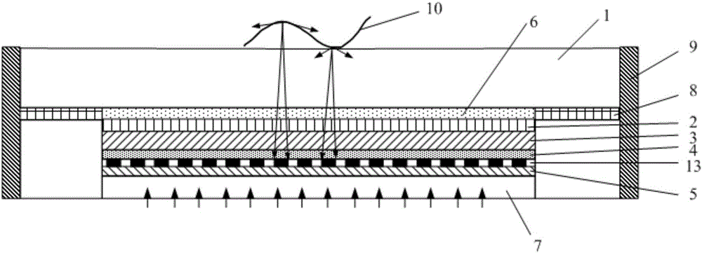
[0036] Such as figure 2 As shown, the display panel includes a glass cove...

Embodiment 2

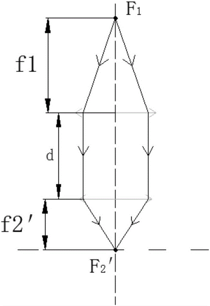
[0052] This embodiment provides a display component, which realizes optical fingerprint recognition based on a display panel, increases the light energy difference between the valley of the fingerprint and the ridge of the fingerprint, and has a more accurate fingerprint recognition effect. The difference between the display assembly of this embodiment and the display assembly of Embodiment 1 lies in that the setting positions of the object-side focal length and the image-side focal length of the curved lens are different.

[0053] In the display assembly of this embodiment, the curvature of the microcylindrical lens in the first curved lens 11 and the microcylindrical lens in the second curved lens 12 can be changed, or the thickness of the glass cover plate 1 can be changed so that the glass cover plate 1 can be lowered. The object-space focal point of the microcylindrical lens on the surface no longer coincides with the upper surface of the glass cover 1 , preferably the obj...

Embodiment 3

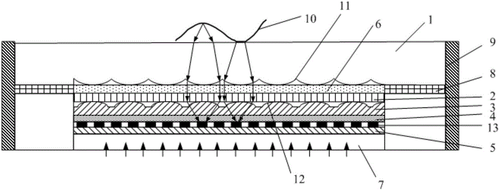
[0066] This embodiment provides a display component, which realizes optical fingerprint recognition based on a display panel, increases the light energy difference between the valley of the fingerprint and the ridge of the fingerprint, and has a more accurate fingerprint recognition effect. The difference between the display assembly in this embodiment and the display assembly in Embodiment 1 or Embodiment 2 is that the display assembly in this embodiment only has the first curved lens 11 .

[0067] Such as Figure 5 As shown in the display assembly, only the lower surface of the glass cover 1 is made into the first curved lens 11 of the microcylindrical lens array with a certain curvature, and the object focus of the microcylindrical lenses on the lower surface of the glass cover 1 is at The inside of the glass cover 1 makes its focal length smaller than the object distance when touched by a finger.

[0068] For the working principle of the display component in this embodime...


PUM


Abstract

The invention belongs to the technical field of display and particularly relates to a display unit and a display device. The display unit comprises a display panel and a backlight, wherein the display panel is divided into a display area and a non-display area and is provided with a graphic acquiring component and an optical processing unit in the display area, the optical processing unit comprises curved lenses capable of converging light, the curved lenses are used for performing converging processing on light, which transmits through the display panel, is shielded by a display side of the display panel and is reflected back, of the backlight, and the processed light is emitted to the graphic acquiring component. The display unit realizes optical type fingerprint recognition on the basis of the display panel, the curved lenses are arranged to converge the light, a light energy difference between valleys and ridges of a fingerprint is increased, and a more accurate fingerprint recognition effect is realized.

Description

technical field [0001] The invention belongs to the field of display technology, and in particular relates to a display component and a display device. Background technique [0002] With the development of fingerprint identification technology, it has been widely used in many fields, such as mobile phones, tablet computers and TVs in electronic equipment terminals; access control and safes in security protection systems. The realization methods of fingerprint collection mainly include optical, capacitive and ultrasonic imaging technologies, among which the optical fingerprint recognition technology has a relatively large recognition range and relatively low cost. [0003] At present, the optical fingerprint recognition technology implemented by liquid crystal display devices, including mobile phones and other mobile terminals, mostly uses a backlight to illuminate the finger, and then the finger diffusely reflects the light beam to the photoelectric sensor to distinguish the...

Claims


Application Information

Patent Timeline
Patent Type & Authority Applications(China)
IPC IPC(8): G06K9/00
CPCG06V40/1324G06V40/1318
Inventor 高健陈小川刘英明王鹏鹏
Owner BOE TECH GRP CO LTD
Why Eureka
Try Eureka