Digital signal system and method for performing digital output by using digital signal system
A digital signal, digital output technology, applied in the field of electronics, can solve the problems of complex operation and high cost
- Summary
- Abstract
- Description
- Claims
- Application Information
AI Technical Summary
Problems solved by technology
Method used
Image

Examples
Embodiment 1
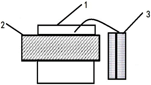
[0024] Such as figure 1 As shown, a digital signal system that generates analog and digital outputs includes a piezoelectric device 3, an electronic display 1 and a metal carrier 2, the piezoelectric device 3 is composed of piezoelectric ceramic sheets and leads, and the electronic display 1 has a Heavy function;
[0025] The metal carrier 2 is fixed on the electronic display 1, the piezoelectric device 3 is located on one side of the metal carrier 2, and the lead wire of the piezoelectric device 3 is located on the upper part of the metal carrier 2; The electrical device 3 is not in contact with the metal carrier 2 .
[0026] Wherein, the precision of the electronic display 1 is 0.5 grams, the distance between the lead wire on the piezoelectric device 3 and the metal carrier 2 is 0.2 cm, and the material of the metal carrier 2 is steel. An insulating plate is placed between the metal carrier 2 and the electronic display 1 .
Embodiment 2
[0028] A digital signal system for generating analog and digital outputs, comprising a piezoelectric device, an electronic display and a metal carrier, the piezoelectric device is composed of piezoelectric ceramic sheets and leads, and the electronic display has a weighing function;
[0029] The metal carrier is fixed on the electronic display, the piezoelectric device is located on one side of the metal carrier, and the lead wire of the piezoelectric device is located on the upper part of the metal carrier; the piezoelectric device and the metal The carrier does not touch.
[0030] Wherein, the precision of the electronic display is 0.5 grams, the distance between the lead wire on the piezoelectric device and the metal carrier is 0.1 cm, and the material of the metal carrier is copper. An insulating plate is placed between the metal carrier and the electronic display.
Embodiment 3
[0032] A digital signal system for generating analog and digital outputs, comprising a piezoelectric device, an electronic display and a metal carrier, the piezoelectric device is composed of piezoelectric ceramic sheets and leads, and the electronic display has a weighing function;
[0033] The metal carrier is fixed on the electronic display, the piezoelectric device is located on one side of the metal carrier, and the lead wire of the piezoelectric device is located on the upper part of the metal carrier; the piezoelectric device and the metal The carrier does not touch.
[0034] Wherein, the precision of the electronic display is 0.5 grams, the distance between the lead wire on the piezoelectric device and the metal carrier is 0.3 cm, and the metal carrier material is hard copper. An insulating plate is placed between the metal carrier and the electronic display.
PUM
 Abstract
Description
Claims
Application Information
 - R&D Engineer
- R&D Manager
- IP Professional
- Industry Leading Data Capabilities
- Powerful AI technology
- Patent DNA Extraction
Browse by: Latest US Patents, China's latest patents, Technical Efficacy Thesaurus, Application Domain, Technology Topic.
© 2024 PatSnap. All rights reserved.Legal|Privacy policy|Modern Slavery Act Transparency Statement|Sitemap