Load distribution method for statically indeterminate structure of dynamic wing surface of aircraft

A load distribution and super-statically indeterminate technology, applied in special data processing applications, instruments, electrical digital data processing, etc., can solve problems such as huge amount of model data, inability to accurately simulate the stiffness of connecting mechanisms, troublesome modification and optimization, etc., to reduce calculation efficiency effect

Active Publication Date: 2016-09-07
XIAN AIRCRAFT DESIGN INST OF AVIATION IND OF CHINA
View PDF5 Cites 19 Cited by
  • Summary
  • Abstract
  • Description
  • Claims
  • Application Information

AI Technical Summary

Problems solved by technology
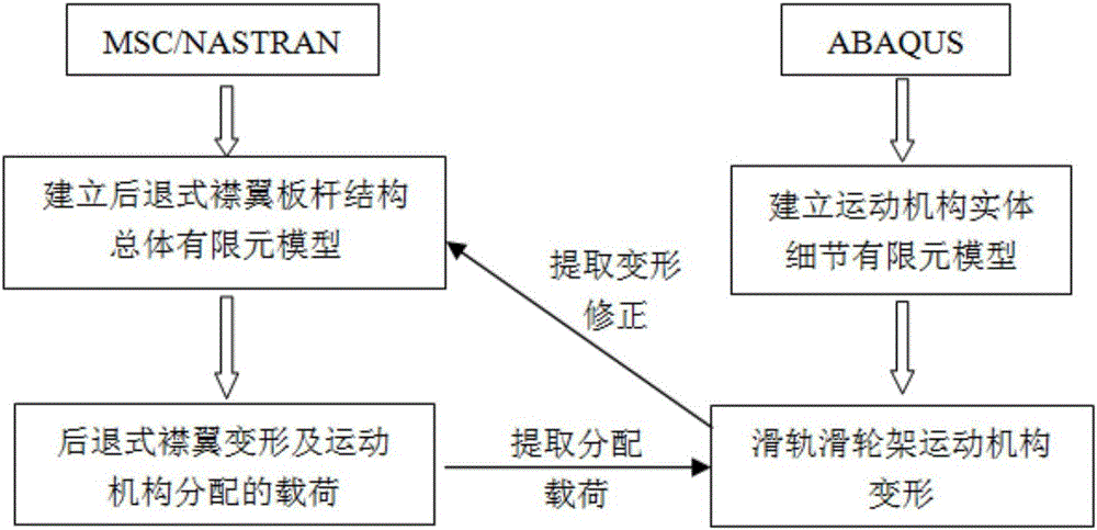
[0003] With the continuous improvement of the overall performance of the aircraft, a new type of dynamic airfoil is designed for the wing, the connection points are changed from 2 to multiple, and the support rods are replaced by complex connection mechanisms, which can be simplified theoretically as a hyperstatically indeterminate multi-point beam. The structure adopts the previous modeling method and uses the NASTRAN software to establish a finite element model for the overall analysis of the bar-plate structure, which cannot accurately simulate the stiffness of the connecting mechanism. For the statically indeterminate structure of the multi-support beam, the stiffness of the connecting mechanism determines the distribution of the load. Modeling methods using only NASTRAN software are no longer suitable for new structures
[0004] In order to accurately simulate the stiffness of the connecting mechanism of the moving airfoil, there is also a technical scheme in the prior art that uses ABAQUS software to establish a finite element model of the overall details of the moving airfoil. However, the model data volume of this scheme is huge, the calculation efficiency is low, and subsequent modification and optimization are extremely troublesome.

Method used


Image

  • Load distribution method for statically indeterminate structure of dynamic wing surface of aircraft
  • Load distribution method for statically indeterminate structure of dynamic wing surface of aircraft
  • Load distribution method for statically indeterminate structure of dynamic wing surface of aircraft

Examples


Embodiment Construction

[0018] In order to make the objectives, technical solutions and advantages of the present invention clearer, the technical solutions in the embodiments of the present invention will be described in more detail below in conjunction with the drawings in the embodiments of the present invention. In the drawings, the same or similar reference numerals denote the same or similar elements or elements having the same or similar functions throughout. The described embodiments are some, but not all, embodiments of the invention. The embodiments described below by referring to the figures are exemplary and are intended to explain the present invention and should not be construed as limiting the present invention. Based on the embodiments of the present invention, all other embodiments obtained by persons of ordinary skill in the art without creative efforts fall within the protection scope of the present invention. Embodiments of the present invention will be described in detail below ...


PUM


Abstract

The invention relates to a load distribution method for a statically indeterminate structure of a dynamic wing surface of an aircraft, and belongs to the field of aircraft structure strength finite element analysis. The method comprises the steps of establishing an overall analysis model of a wing surface body by adopting NASTRAN; establishing a detail analysis finite element model of a connection mechanism by adopting ABAQUS; correcting load distribution in the overall analysis model by changing the stiffness of the connection mechanism with the detail analysis finite element model; obtaining new stress and strain in the overall analysis model by using new load distribution, wherein the stress and strain determine the stiffness correction process; and performing repeated iteration in this way to obtain relatively accurate load distribution. Through the method, the problem in force transmission distribution of a pneumatic load on the wing surface body to the connection mechanism in the statically indeterminate structure of the dynamic wing surface of the aircraft is successfully solved; and the method can be applied to load distribution of the statically indeterminate structures of other parts.

Description

technical field [0001] The invention belongs to the field of finite element analysis of aircraft structure strength, and in particular relates to a load distribution method for a statically indeterminate structure of an aircraft dynamic wing surface. Background technique [0002] The structural form of the existing aircraft's dynamic wing surface is relatively simple, and the statically indeterminate structure is composed of the wing surface body connected with the support rods. The analysis method is the same as that of the ordinary fixed wing surface. The NASTRAN software is used to establish the finite element model for the overall analysis of the rod-plate structure. The distribution of load transmission from the airfoil body to the support bar is obtained through analysis and calculation. [0003] With the continuous improvement of the overall performance of the aircraft, a new type of dynamic airfoil is designed for the wing, the connection points are changed from 2 to...

Claims


Application Information

Patent Timeline
Patent Type & Authority Applications(China)
IPC IPC(8): G06F17/50
CPCG06F30/15G06F30/23
Inventor 魏洪杜凯范瑞娟郑茂亮鬲钰焯
Owner XIAN AIRCRAFT DESIGN INST OF AVIATION IND OF CHINA
Why Eureka
Try Eureka