Robot system having robot operated in synchronization with bending machine

A robotic system and bending processing technology, applied in the field of robotic systems, can solve problems affecting processing quality, workpiece bending, etc.

Inactive Publication Date: 2016-09-14
FANUC LTD
View PDF4 Cites 13 Cited by
  • Summary
  • Abstract
  • Description
  • Claims
  • Application Information

AI Technical Summary

Problems solved by technology

[0006] On the other hand, in the method for the robot to release or hold the workpiece, their timing needs to be adjusted, especially in the case of a large workpiece, if the robot releases the workpiece, the workpiece will be bent during processing, which may affect the processing quality

Method used


Image

  • Robot system having robot operated in synchronization with bending machine
  • Robot system having robot operated in synchronization with bending machine
  • Robot system having robot operated in synchronization with bending machine

Examples


no. 1 example

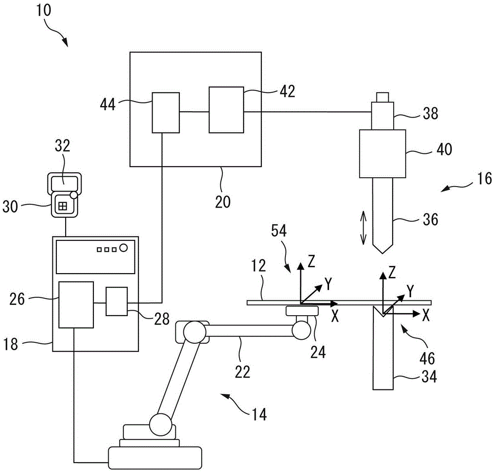
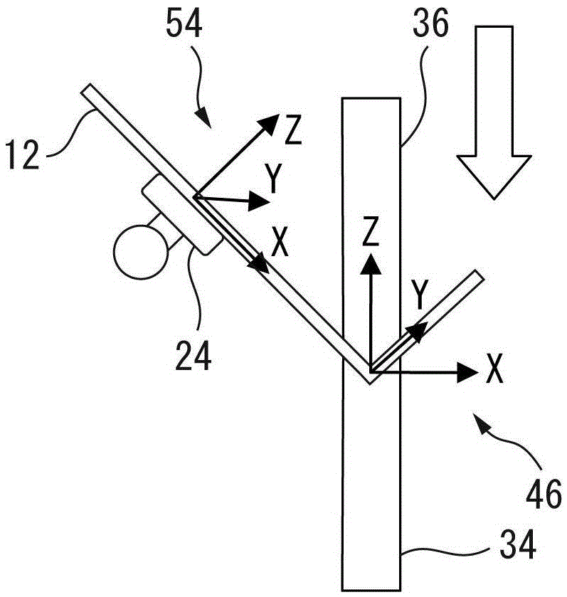
[0041] First, if figure 1 or image 3 As shown, the user coordinate system 46 for the rotation axis (rotation center line) of the bending operation in the predetermined bending process is set. For example, the user coordinate system 46 can be set by the operator inputting the position and angle of each axis of the robot 14 to the teaching operation panel 30 , Figure 4 This input example (screen 32 of the teaching operation panel 30) is shown. In addition, in figure 1 In our example, the user coordinate system 46 is set so that its Y axis is aligned with the edge of the die 34 (in figure 1 The center extends vertically with the paper surface).

[0042] Next, if Figure 5 As shown, in the teaching program 48 of the robot 14, the processing start position P[1] and the motion form are defined, the bending processing command (BEND_START) is added, and the rotation angle (θ) and the rotation around the bending processing (bending motion) are specified. The angular velocity (h...

no. 2 example

[0048] First, if figure 1 or Figure 7 As shown, the user coordinate system 46 for the rotation axis (rotation center line) of the bending operation in the predetermined bending process is set. Like the first embodiment, for example, the user coordinate system 46 can be set by the operator inputting the position and angle of each axis of the robot 14 to the teaching pendant 30 . Figure 4 This input example (screen 32 of the teaching operation panel 30) is shown. In addition, in figure 1 In our example, the user coordinate system 46 is set so that its Y axis is aligned with the edge of the die 34 (in figure 1 The center extends vertically with the paper surface).

[0049] Next, if Figure 8 As shown, in the teaching program 56 of the robot 14, the rotation angle (θ) of the bending process (bending action), the angular velocity (here, 90 deg / sec) of the command line 50 around the rotation axis, and the rotation angle of the user coordinate system 46 are specified. The rad...

no. 3 example

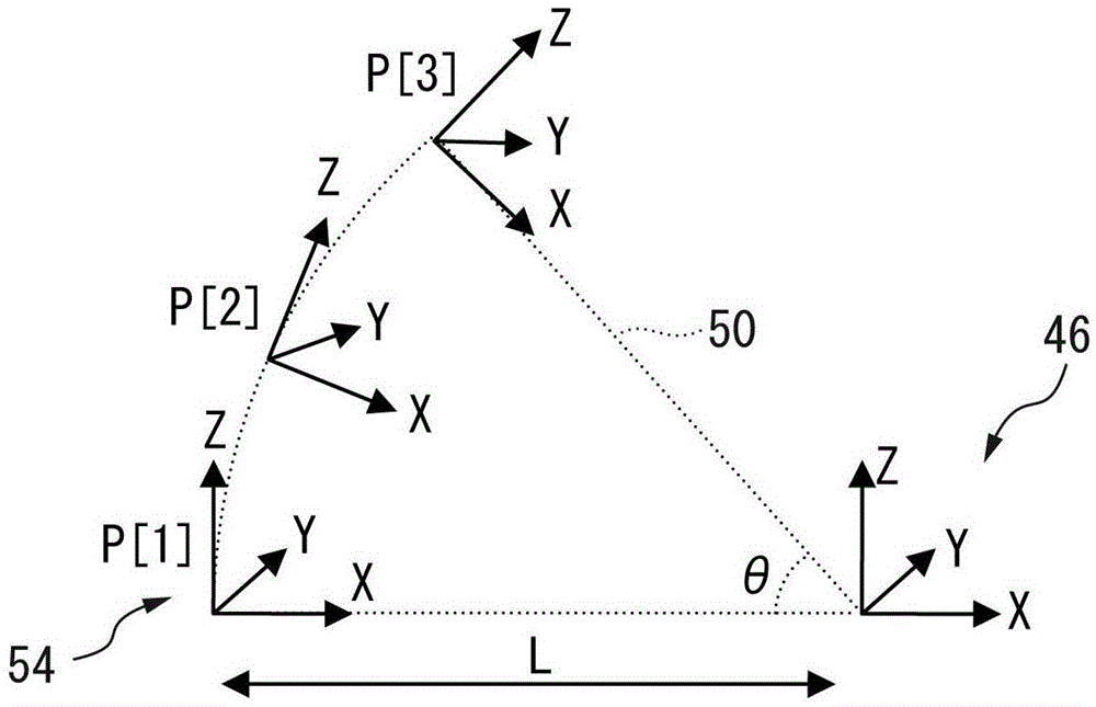
[0056] First, if Figure 8 As shown, in the teaching program 56 of the robot 14, the rotation angle (θ) of the bending process (bending action), the angular velocity (here, 90 deg / sec) of the command line 50 around the rotation axis, and the X of the user coordinate system 46 are specified. The radius (L) of the bending process in the axial direction and the rotation angle around the Z axis of the user coordinate system 46 Here, the machining start position P[1] refers to the position of the workpiece 12 held by the robot 14, as in the first embodiment. Teach in the robot teach program 48 .

[0057] Through the above processing, the definition Figure 7 A user coordinate system 46 for the axis of rotation (center line of rotation) of the predetermined bending process is shown. In the teaching program 56, the processing start position P[1] and the motion form are further defined and a bending processing command (BEND_START) is added, thereby generating Figure 7The interna...


PUM


Abstract

A robot system for carrying out a bending process with respect to a workpiece held by a robot, in which an arc interpolation motion of the robot can be easily and precisely taught. A user coordinate system is set so as to specify a rotation axis of the bending motion in the bending process by inputting the position and / or angle of each axis of the robot to a teaching pendant by the operator. Next, in a teaching program of the robot, a process start position and an operation form are defined so as to add a bending process command, and a rotation angle of the bending process and an angular velocity of a command line about the rotation axis are designated. By virtue of this, an internal program for carrying out an arc interpolation motion by the robot is generated in a robot controlling part.

Description

technical field [0001] The present invention relates to a robot system that performs bending while holding a workpiece in synchronization with a bending machine. Background technique [0002] Generally, in bending machines called trigger benders, bending machines, etc., the position and posture of the robot workpiece (hereinafter also referred to as position and posture) are detected by sensors, and the robot moves the manipulator to the detected position and posture to hold and take out the workpiece. . As an example of known technology related thereto, Japanese Patent Application Laid-Open No. 06-015370 describes a method and an apparatus for following a bending motion in order to hold a workpiece in the gripper of a bending robot installed in a bending machine. The trajectory of the circular interpolation of the bending robot action is obtained accurately, the cutting amount of the blade tip portion of the bending machine is calculated according to the bending angle of t...

Claims


Application Information

Patent Timeline
Patent Type & Authority Applications(China)
IPC IPC(8): B21D7/06B21D5/01B25J11/00
CPCB21D5/01B21D7/06B25J11/005B21D5/02B21D5/0281G05B2219/39105B25J9/1664B21D5/006Y02P90/02
Inventor 高山佑辅
Owner FANUC LTD
Why Eureka
Try Eureka