A general-purpose robot with a rotating execution end

A technology for executing terminal and robot, which is applied in the field of robotics and can solve problems such as difficult to meet actual operation.

Inactive Publication Date: 2018-05-11
烟台盛创智能科技有限公司
View PDF10 Cites 0 Cited by
  • Summary
  • Abstract
  • Description
  • Claims
  • Application Information

AI Technical Summary

Problems solved by technology

In the light-duty six-axis universal robot in the prior art, the forearm can only drive the execution end installed at the end of the forearm to rotate, which is difficult to meet the needs of actual operation

Method used


Image

  • A general-purpose robot with a rotating execution end
  • A general-purpose robot with a rotating execution end
  • A general-purpose robot with a rotating execution end

Examples


Embodiment Construction

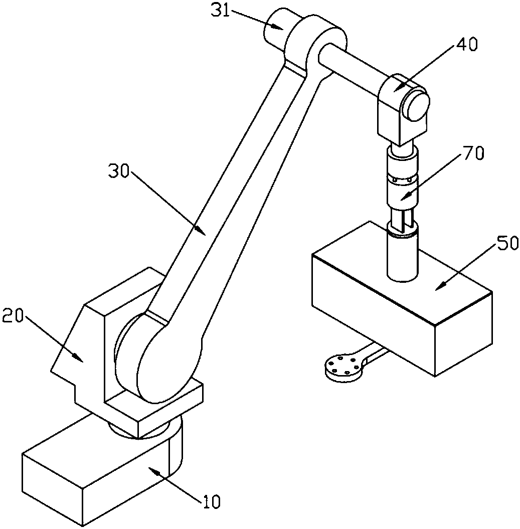
[0035] Such as figure 1 As shown, a general-purpose robot provided with a rotating execution end includes a base body 10, a waist swivel part 20 pivotally connected to the base body 10, a boom 30 pivotally connected to the waist swivel part 20, and a boom 30 fixed to the bottom body. The forearm 40 on the output shaft of the sixth motor 31 at one end, the waist rotating part 20 rotates around the base body 10, and the big arm 30 rotates around the waist rotating part 20;

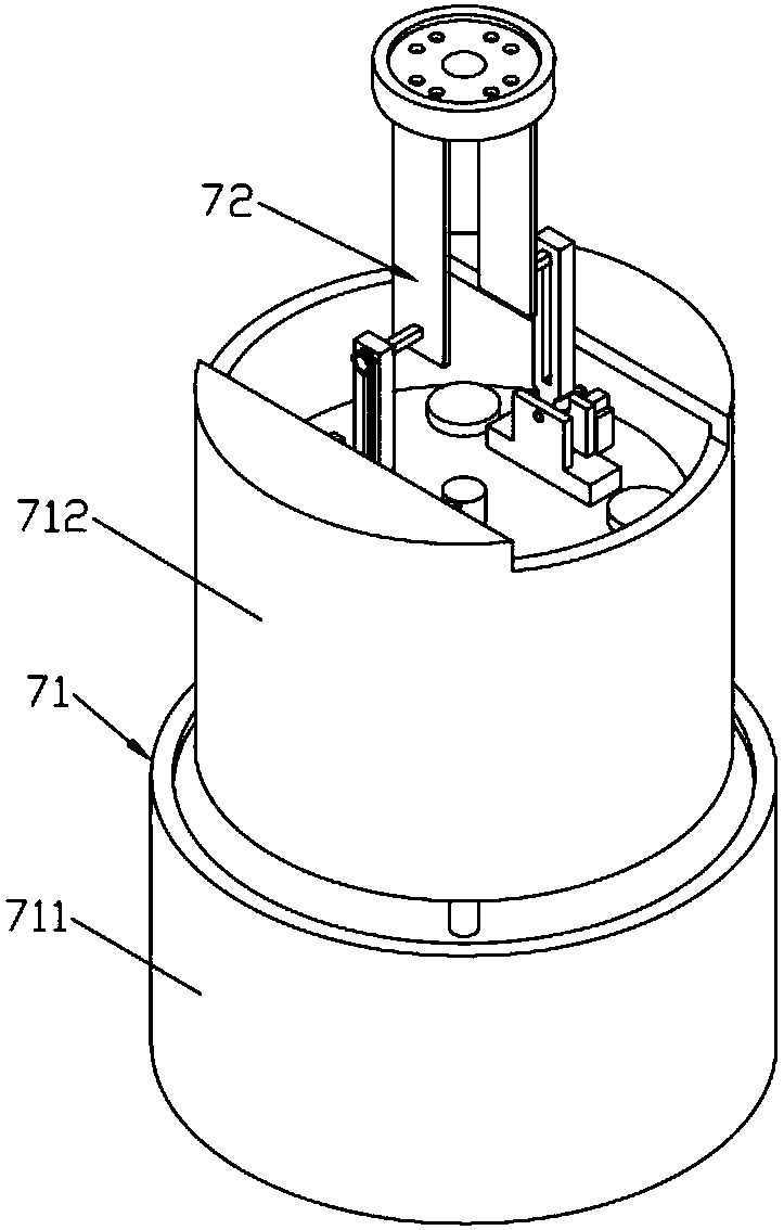
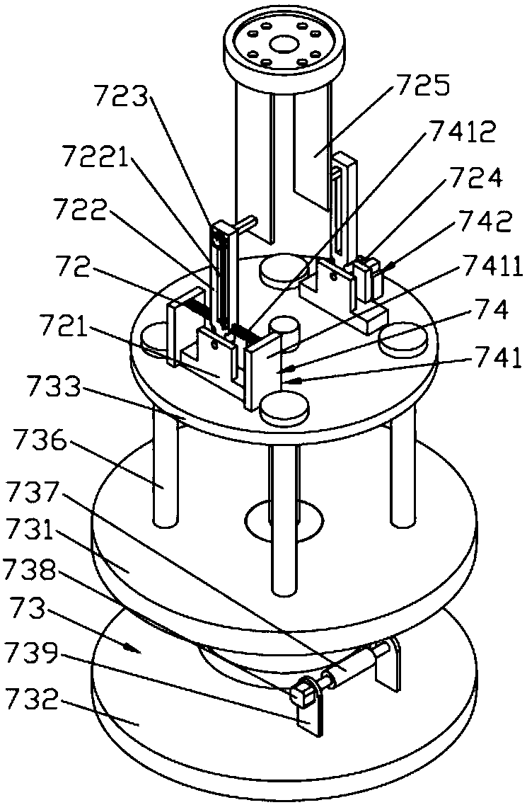
[0036] Such as Figure 1 to Figure 8 As shown, the forearm is provided with an extension arm 70, and the extension arm includes a support body 71 fixedly connected to the forearm, a first telescopic mechanism 73 installed on the support body, and a swing mechanism hinged on the first telescopic mechanism. 72. Slide the second telescopic mechanism arranged in the sliding groove of the swing mechanism 72 and the reset device 74 installed on the swing mechanism 72;

[0037] Such as Figure 1 to Figure 8 As s...


PUM


Abstract

The invention discloses a universal robot provided with a rotating execution tail end. An extending arm is arranged on each forearm of the robot. Each extending arm comprises a support body fixedly connected with the corresponding forearm, a first stretching mechanism installed on the support body, a swinging mechanism hinged to the first stretching mechanism, a second stretching mechanism arranged inside a sliding groove of the swinging mechanism in a sliding mode and a reset device installed on the swinging mechanism. A rotating mechanical hand is fixedly arranged at the front end of each extending arm. Each rotating mechanical hand comprises a pair of suction cup set and a driving mechanism for driving the suction cup set to rotate, wherein the driving mechanism comprises a base, a rotating assembly, a rotating driving device and a buckle assembly. The first stretching mechanisms can lengthen or shorten the corresponding stretching arms and increase or decrease the total length of the extending arms so as to adapt to various working conditions.

Description

technical field [0001] The invention relates to the technical field of robots, in particular to a general-purpose robot provided with a rotating execution end. Background technique [0002] The invention patent application with the application number CN201210566463.5 discloses a light-duty six-axis universal robot. The drive motor for the fifth axis and the drive motor for the sixth axis are placed in the shaft seat protection box; the housing of the arm rod and the housing of the arm extension rod are respectively fixed at the front and rear of the arm reducer, and the sleeve of the sixth axis is in the fifth shaft, the fifth shaft is inserted into the fourth shaft, the fourth shaft is inserted into the housing of the forearm rod, the reducer of the small arm and the housing of the extension rod of the small arm, the fourth shaft, the fifth shaft and the sixth shaft A fourth shaft driven gear, a fifth shaft driven gear and a sixth shaft driven gear are respectively fixed o...

Claims


Application Information

Patent Timeline
Patent Type & Authority Patents(China)
IPC IPC(8): B25J18/04
CPCB25J18/007B25J18/04
Inventor 王一轩王中进付淑珍
Owner 烟台盛创智能科技有限公司
Why Eureka
Try Eureka