Eureka AIR delivers breakthrough ideas for toughest innovation challenges, trusted by R&D personnel around the world.

A PWM output fault diagnosis method and system

A technology for outputting faults and diagnosis results. It is applied to instruments, measuring devices, measuring electricity, etc. It can solve problems such as uncontrollable delay time, avoid diagnosis errors and improve real-time performance.

Active Publication Date: 2019-03-12
BEIJING JINGWEI HIRAIN TECH CO INC
View PDF6 Cites 0 Cited by
  • Summary
  • Abstract
  • Description
  • Claims
  • Application Information

AI Technical Summary

Problems solved by technology

Since the delay time is uncontrollable, it is easy to cause errors

Method used


Image

  • A PWM output fault diagnosis method and system
  • A PWM output fault diagnosis method and system
  • A PWM output fault diagnosis method and system

Examples


Embodiment Construction

[0079] The following will clearly and completely describe the technical solutions in the embodiments of the present invention with reference to the accompanying drawings in the embodiments of the present invention. Obviously, the described embodiments are only some, not all, embodiments of the present invention. Based on the embodiments of the present invention, all other embodiments obtained by persons of ordinary skill in the art without making creative efforts belong to the protection scope of the present invention.

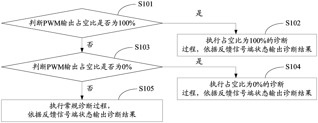
[0080] Such as figure 1 Shown, be a kind of PWM output fault diagnosis method disclosed by the present invention, comprising:

[0081] S101, judging whether the duty cycle of the PWM output is 100%, if so, proceed to S102, if not, proceed to S103:

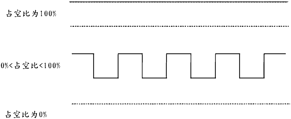
[0082] Such as figure 2 As shown, there are three situations of PWM output, when the duty cycle is 100%, the PWM output is always high level, when the duty cycle is 0%, the PWM output is always low level, when t...


PUM


Abstract

The invention discloses a PWM output fault diagnosis method. The method includes the steps that whether the PWM output duty ratio is 100% or not is judged; if yes, the diagnosis process with the duty ratio being 100% is executed, and a diagnosis result is output according to the state of a feedback signal side; if not, whether the PWM output duty ratio is 0% or not is judged, if yes, the diagnosis process with the duty ratio being 0% is executed, and a diagnosis result is output according to the state of the feedback signal side; if not, the conventional diagnosis process is executed, and a diagnosis result is output according to the state of the feedback signal side. Fault diagnosis can be achieved by reading the state of the feedback signal side at different duty ratios, and the real-time performance of PWM output fault diagnosis is improved. The invention further discloses a PWM output fault diagnosis system.

Description

technical field [0001] The present invention relates to the technical field of fault diagnosis, in particular to a PWM (Pulse Width Modulation, pulse width modulation) output fault diagnosis method and system. Background technique [0002] At present, for the diagnosis of the PWM output fault, usually by collecting the state of the feedback signal end, comparing the state of the feedback signal end with the state of the PWM output end, and outputting the diagnosis result. In the existing way of comparing the state of the feedback signal end with the state of the PWM output end, there is a certain hardware delay between the PWM output end and the feedback signal end. Since the delay time is uncontrollable, it is easy to cause errors. Contents of the invention [0003] The invention provides a PWM output fault diagnosis method, which can realize fault diagnosis by reading the states of feedback signal terminals under different duty ratios, and improves the real-time perform...

Claims


Application Information

Patent Timeline
Patent Type & Authority Patents(China)
IPC IPC(8): G01R31/00
CPCG01R31/00
Inventor 杨东耳
Owner BEIJING JINGWEI HIRAIN TECH CO INC
Why Eureka
Eureka Blog
Learn More