Lever gravity pneumatic generator set
A pneumatic generator and gravity technology, applied in the direction of machines/engines, mechanisms for generating mechanical power, mechanical equipment, etc., can solve problems that cannot meet human clean, energy-saving and applicable requirements
Inactive Publication Date: 2016-10-05
张久然
View PDF0 Cites 0 Cited by
- Summary
- Abstract
- Description
- Claims
- Application Information
AI Technical Summary
Problems solved by technology
[0002] At present, the traditional general-purpose power generation equipment has various shortcomings that cannot meet the requirements of clean, energy-saving and applicable human beings.
Method used
View moreImage
Smart ImageViewing Examples

Examples
Embodiment Construction
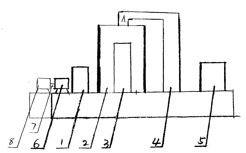
[0017] In Fig. 1, the input end of 1 is connected with the output end of 2, the input end of 2 is connected with 4, 8 is connected with 6, and the remaining parts are fixed on the relevant parts of the assembly 7. press again picture As shown mount the union on the picture On the shown 3, when the 8 in the cylinder starts to move after the 6 starts the 5, the air pressure will be generated and pressed into the 9, and when the 9 reaches 8 air pressure, the motor 2 can be pushed and the 1 can be driven to work.
Login to View More PUM
 Abstract
The invention discloses a pneumatic generator set conforming with the lever gravity principle. The technical scheme is shown in the drawing, and in the diagrammatic drawing, a connecting shaft 7 is connected with a pneumatic motor 6; the input end of the pneumatic motor 6 is connected with a gas outlet valve of a high-pressure bin 1; the input end of the high-pressure bin 1 is connected with a gas outlet valve of a gravity cylinder 2; a fixed piston 3 is fixed to a machine tool; the upper end of a lever 4 is fixedly connected with a connecting device of a connector A; the input end of the lever 4 is connected with a power source 5. When the power source 5 drives the lever 4 to move, the gravity cylinder 2 can be driven to move up and down so as to generate air pressure and push the air pressure into the high-pressure bin 1; and when the air pressure in the high-pressure bin 1 reaches eight, the pneumatic motor 6 can be started to drive a generator 8 to work.
Description
Technical field: [0001] The invention relates to a power generating device, a lever and a gravity gas generating system, in particular to a lever gravity principle, a pneumatic generator. technical background: [0002] At present, the traditional general-purpose power generation equipment has various shortcomings and cannot meet the requirements of clean, energy-saving and applicable human beings. Invention content: [0003] The invention creates a clean, energy-saving and high-efficiency lever gravity pneumatic power generation equipment. Invention content: [0004] The purpose of the present invention is to create a clean, applicable, energy-saving and high-efficiency lever gravity pneumatic power generating equipment. [0005] The technical solution adopted by the present invention to solve the technical problem includes a generator, a gravity gas-making system, a high-pressure gas storage bin and an air motor, and its features also include a lever and a power system...
Claims
Login to View More Application Information
Patent Timeline
 Patent Type & Authority Applications(China)
IPC IPC(8): F03G7/00
Inventor 张久然
Owner 张久然