Induced draft channel structure of rail traffic vehicle cab

A rail transit and driver's cab technology, applied to locomotives and other directions, can solve problems such as the inability to effectively adjust the air volume in the driver's cab and the sound of large airflow

Active Publication Date: 2016-10-12
CRRC NANJING PUZHEN CO LTD
View PDF12 Cites 8 Cited by
  • Summary
  • Abstract
  • Description
  • Claims
  • Application Information

AI Technical Summary

Problems solved by technology

[0004] The disadvantages brought about by the above structure are: first, when the demand for air volume in the driver's cab is small, due to the pressure of the air conditioner in the passenger room, more wind will still be forced into the driver's cab, and the air volume in the driver's cab cannot be effectively adjusted
[0005] Second, the airflow is sent into the driver's cab with a relatively large dynamic pressure, and there is a loud airflow sound

Method used


Image

  • Induced draft channel structure of rail traffic vehicle cab
  • Induced draft channel structure of rail traffic vehicle cab

Examples


Embodiment Construction

[0020] The present invention will now be described in further detail with reference to the drawings. These drawings are all simplified schematic diagrams, which merely illustrate the basic structure of the present invention in a schematic manner, so they only show the structures related to the present invention.

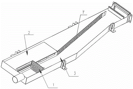
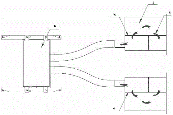
[0021] Such as figure 1 with figure 2 As shown, the guide air duct structure of the rail transit vehicle cab includes a main air duct body. One end of the main air duct body is provided with an air inlet and the other end is provided with an air outlet. The air inlet and the passenger compartment air duct are air-conditioned The air source processed by the unit is connected, and the air outlet is connected to the cab ventilation unit through a pipe; it is characterized in that a deflector is provided in the main air duct, and the deflector makes the air inlet and the air outlet between A diversion channel is formed, and a resistance plate is arranged on the diversion ...


PUM


Abstract

The invention relates to an induced draft channel structure of a rail traffic vehicle cab. The induced draft channel structure comprises a main air duct body, wherein an air inlet is formed in one end of the main air duct body, an air outlet is formed in the other end of the main air duct body, the air inlet is communicated with an air source treated by an air conditioning unit in a passenger carriage air duct, and the air outlet is connected with a cab ventilation unit through a pipeline; and the induced draft channel structure is characterized in that a guide plate is arranged in the main air duct, the guide plate allows a guide passage to be formed between the air inlet and the air outlet, the end of the guide passage, adjacent to the air outlet, is provided with a resistance plate perpendicular to the flowing direction of the wind, and one side of the resistance plate is provided with a static pressure cavity. The induced draft channel structure can effectively suppress the action of the dynamic pressure of the passenger carriage air conditioning unit and control the air volume sent into a cab.

Description

Technical field [0001] The invention relates to an air guide structure for a rail transit vehicle cab. Background technique [0002] At present, the cab ventilation unit of subway vehicles is mostly used in the cab, and an air duct is set between the ventilation unit and the air duct of the passenger compartment close to the cab. When the ventilation unit is operating, the air processed by the air conditioning unit in the passenger compartment air duct near the driver's cab is introduced into the driver's cab through the air duct. The subway project has requirements for the maximum air supply volume in the driver’s cab. If there is no ventilation unit, only the air intake duct and the air delivery grille are set, and the air is sent into the driver’s cab through the air pressure in the passenger compartment close to the driver’s cab. The air volume is usually not up to the requirement. [0003] The existing implementation scheme is generally that the air processed by the air cond...

Claims


Application Information

Patent Timeline
Patent Type & Authority Applications(China)
IPC IPC(8): B61C17/04
CPCB61C17/04
Inventor 王业龚继如孙方叶佳陈奇宁宝焕沙文兵
Owner CRRC NANJING PUZHEN CO LTD
Why Eureka
Try Eureka