Vertical laminar flow system of microenvironment

A micro-environment, laminar flow technology, applied in electrical components, semiconductor/solid-state device manufacturing, circuits, etc., can solve problems such as unfavorable overall area, local micro-environment cannot achieve cleanliness, control, etc., and achieve the effect of convenient control

Inactive Publication Date: 2011-11-23
BEIJING SEVENSTAR ELECTRONICS CO LTD
View PDF11 Cites 3 Cited by
  • Summary
  • Abstract
  • Description
  • Claims
  • Application Information

AI Technical Summary

Problems solved by technology

However, this structure is not conducive to the control of the entire area, often making the local microenvironment less than the required cleanliness

Method used


Image

  • Vertical laminar flow system of microenvironment
  • Vertical laminar flow system of microenvironment
  • Vertical laminar flow system of microenvironment

Examples


Embodiment Construction

[0032] The specific implementation manners of the present invention will be further described in detail below in conjunction with the accompanying drawings and embodiments. The following examples are used to illustrate the present invention, but are not intended to limit the scope of the present invention.

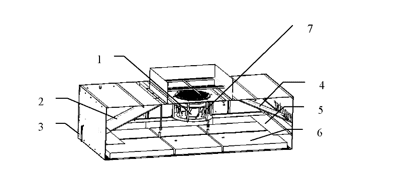
[0033] like figure 1 Shown is a schematic diagram of an embodiment of the vertical laminar flow system of the microenvironment of the present invention, which includes a cuboid-shaped chamber, a fan module 1, a flow guiding device 2, a flow equalizing device 5, a filter module 6, and the like.

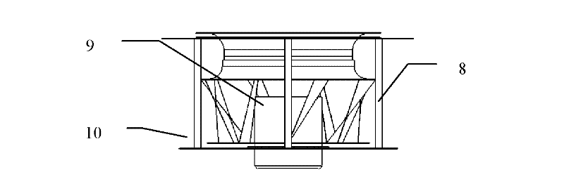
[0034] The fan module 1 passes through the hoisting unit 7 (such as Figure 2a Shown) the fan hoisting screw rod (also can be rope) 8 is arranged on the inner top surface (ceiling) or inner side of chamber. There can be one or more centrifugal fans arranged in the fan module 1 . The air volume at the air inlet is uniformly controlled by the fan module 1 in the whole area, and th...


PUM


Abstract

The invention discloses a vertical laminar flow system of a microenvironment. The vertical laminar flow system comprises a chamber with a cuboidal shape, a fan module, a deflector, a flow equalization device, a filter module and a keel, wherein at least one fan is arranged in the fan module; the fan module is arranged in the chamber; the deflector is arranged in the chamber; the flow equalization device is arranged below the fan module and the deflector in the chamber; and the filter module and the keel are arranged on an inner ground surface in the chamber. The vertical laminar flow system of the microenvironment uniformly controls the air volume of an air inlet of a vertical laminar flow of the whole area by the fan module, and performs flow field optimization on the inner chamber by the coaction of the deflector and the flow equalization device to blow an air flow in the chamber uniformly and consistently into a lower-layer space by the air inlet surface of the filter module to obtain a flow field with relatively higher consistency, thereby making the cleanness of a local microenvironment meet requirements.

Description

technical field [0001] The invention relates to the field of semiconductor equipment, in particular to a vertical laminar flow system of a microenvironment. Background technique [0002] At present, semiconductor equipment manufacturers all adopt the vertical laminar flow generation system of FFU (Fan Filter Unit), which divides the required micro-environmental area into several separate areas, and each area contains at least one FFU, these units together form a vertical laminar flow system. Each FFU contains its own fan module and filter module. The fan module is located above and the filter module is located below. However, this structure is not conducive to controlling the entire area, and often makes the local micro-environment less than the required cleanliness. Contents of the invention [0003] (1) Technical problems to be solved [0004] The object of the present invention is to provide a laminar vertical system of micro-environment considering the whole area as...

Claims


Application Information

Patent Timeline
Patent Type & Authority Applications(China)
IPC IPC(8): H01L21/00
Inventor 韩丽娜吴仪
Owner BEIJING SEVENSTAR ELECTRONICS CO LTD
Why Eureka
Try Eureka