A Method for Tracing the Temperature Difference and Density Flow in Stratified Reservoirs

A technology of density flow and reservoir with temperature difference, applied in special data processing applications, instruments, electrical digital data processing, etc., can solve density changes, it is difficult to distinguish the trajectory of density flow, and the movement law of mixed solution cannot fully reflect the temperature difference Problems such as reflow movement rules, to achieve the effect of ensuring accuracy

Active Publication Date: 2018-07-24
HOHAI UNIV
View PDF5 Cites 0 Cited by
  • Summary
  • Abstract
  • Description
  • Claims
  • Application Information

AI Technical Summary

Problems solved by technology

Due to the difference between the water temperature in the underflow and the water temperature in the ambient water body, it can be easily distinguished in the numerical simulation. Generally, the point where the density gradient is zero is taken as the interface between the underflow and the ambient water body; The interlaminar flow is limited by the fact that the water temperature of the interlaminar flow is almost the same as that of the surrounding environment. From the perspective of water temperature, it is difficult to distinguish the trajectory of the hyperpycnal flow intruding into the environmental water body.
The common practice now is to add a tracer, such as potassium permanganate solution, or other tracers that can be distinguished by color, in the incoming flow, and distinguish the boundary line by the color of the tracer; this can indeed It shows interlaminar flow water body, but the density of the incoming water body added with potassium permanganate solution changes accordingly, and thus the movement law of the mixed solution cannot fully reflect the pure temperature difference and gravity flow in the stratified reservoir environment Movement Law of Interlaminar Flow Formed in Water Body

Method used


Image

  • A Method for Tracing the Temperature Difference and Density Flow in Stratified Reservoirs
  • A Method for Tracing the Temperature Difference and Density Flow in Stratified Reservoirs
  • A Method for Tracing the Temperature Difference and Density Flow in Stratified Reservoirs

Examples


Embodiment 1

[0025] Embodiment one: if Figure 1-5 As shown, it mainly includes the following steps:

[0026] Step 1: According to the actual topography of the reservoir, collect the water depth and the length and width of the liquid surface at each location of the reservoir to establish a reservoir model diagram suitable for numerical calculation, and divide the reservoir model diagram into grid-like graphics and store them in the computer ;

[0027] Step 2: Create the basic equations involved in the process of water flow, including: continuity equation, momentum equation, energy equation, and select the k-εRNG turbulence model for calculation;

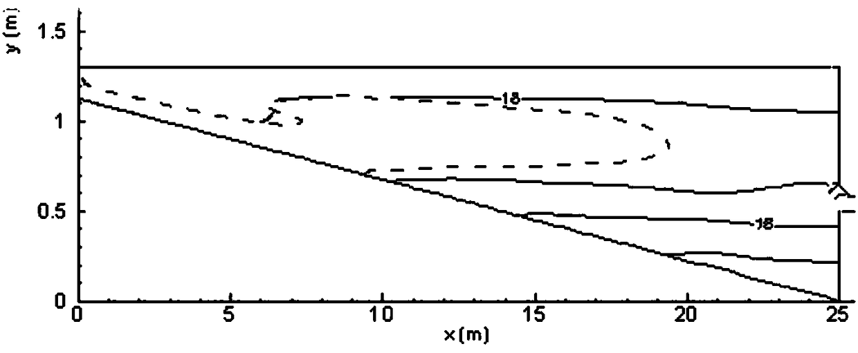
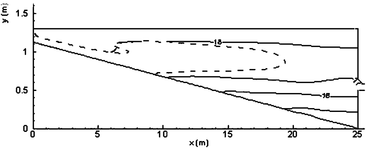
[0028] Step 3: Set the physical and thermodynamic properties of the incoming water body in software such as ansys or fluent software according to the actual situation of the incoming water body, including density, specific heat, thermal conductivity, thermal expansion coefficient, and viscosity coefficient; figure 2 The water temperature distr...

Embodiment 2

[0036] Embodiment two: the steps of the present invention are as follows:

[0037] Step 1: According to the actual topography of the reservoir, collect the water depth and the length and width of the liquid surface at each location of the reservoir to establish a reservoir model diagram suitable for numerical calculation, and divide the reservoir model diagram into grid-like graphics and store them in the computer ;

[0038] Step 2: Create the basic equations involved in the process of water flow, including: continuity equation, momentum equation, energy equation, and select the k-εRNG turbulence model for calculation;

[0039] Step 3: Set the physical and thermodynamic properties of the incoming water body in software such as ansys or fluent software according to the actual situation of the incoming water body, including density, specific heat, thermal conductivity, thermal expansion coefficient, and viscosity coefficient;

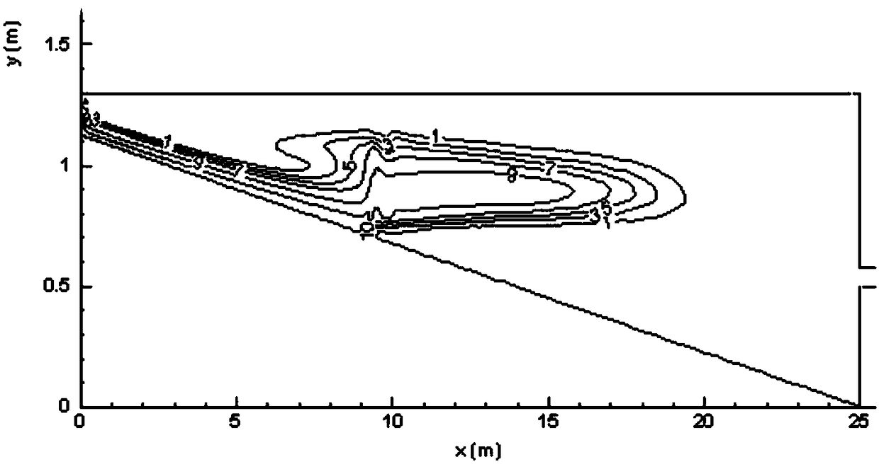
[0040] Step 4: Add a small amount of any other sol...

Embodiment 3

[0044] Embodiment three: the first step: according to the actual topography of the reservoir, the water depth of each location of the reservoir and the length and width data of the liquid surface are collected to establish a reservoir model diagram suitable for numerical calculation, and the reservoir model diagram is divided into grid-like graphics stored in a computer;

[0045] Step 2: Create the basic equations involved in the process of water flow, including: continuity equation, momentum equation, energy equation, and select the k-εRNG turbulence model for calculation;

[0046] Step 3: Set the physical and thermodynamic properties of the incoming water body in software such as ansys or fluent software according to the actual situation of the incoming water body, including density, specific heat, thermal conductivity, thermal expansion coefficient, and viscosity coefficient;

[0047] Step 4: Add a small amount of any other solution as a tracer in the incoming stream, such ...


PUM


Abstract

The invention discloses a stratified reservoir thermal density flow tracing method mainly comprising the following steps: drawing landform and grid and inputting information into computer software, selecting a basic equation needed by the flowing incoming flow, and selecting a turbulent model and parameters complying with calculation requirements; setting physical and thermodynamics properties of the incoming flow body according to the real conditions of the incoming flow body; adding a tracking agent in the computer software, and calculating a tracking agent motion convection dispersion equation and parameters thereof; setting the incoming flow tracing agent concentration A; selecting B% of the incoming flow tracking agent concentration as the contour border of the thermal interflow when the calculation is over, thus clearly displaying shape features like the interflow specific thickness and the central line specific position. The advantages are that the novel method can clearly display thermal interflow motion conditions including shape, thickness and central position, thus ensuring calculating accuracy.

Description

technical field [0001] The invention belongs to the technical field of water flow detection, in particular to a method for tracing the temperature difference and heavy flow of stratified reservoirs. Background technique [0002] In stratified reservoirs, when the density of the incoming water body is higher than the surface density of the ambient water body, a subsurface flow will form near the reservoir inlet. According to the density of incoming water body and the density of stratified reservoir environment water body, there will be two kinds of movement conditions in different forms: the bottom flow that moves along the bottom slope and the interlaminar flow that breaks away from the bottom slope and intrudes into the environmental water body at the separation point. Due to the difference between the water temperature in the underflow and the water temperature in the ambient water body, it can be easily distinguished in the numerical simulation. Generally, the point where...

Claims


Application Information

Patent Timeline
Patent Type & Authority Patents(China)
IPC IPC(8): G06F17/50
CPCG06F30/367G06F2119/08
Inventor 王婷陈辉陈波
Owner HOHAI UNIV
Why Eureka
Try Eureka