A fast transfer device and method with adjustable landing point based on rotary form

A transfer device and drop-point technology, applied in the directions of transportation and packaging, conveyor objects, conveyors, etc., can solve the problems of inability to transfer long-distance, affect the production cycle, affect the production cost, etc., and reduce the logistics operation cost and work efficiency. High and easy-to-operate effect

Inactive Publication Date: 2018-10-09
SOUTH CHINA UNIV OF TECH
View PDF4 Cites 0 Cited by
  • Summary
  • Abstract
  • Description
  • Claims
  • Application Information

AI Technical Summary

Problems solved by technology

[0002] With the rise and rapid development of smart factories, modern factories have basically realized unmanned operation, which requires more complex electromechanical structure assembly lines to complete various processes that could only be completed manually before; especially in logistics transshipment. The requirement of transshipment between places is not uncommon, so many transshipment machines have been born, but most of them use the movement of serial manipulators to achieve the purpose of transshipment, but there are also many problems, such as the inability to transship over long distances, etc.
[0003] The products in the factory often have to go through multiple processes, so each process may need to be carried out in different places. At this time, the goods need to be transshipped. The time of transshipment also affects the production cycle, which in turn affects the production cost.

Method used


Image

  • A fast transfer device and method with adjustable landing point based on rotary form
  • A fast transfer device and method with adjustable landing point based on rotary form
  • A fast transfer device and method with adjustable landing point based on rotary form

Examples


Embodiment

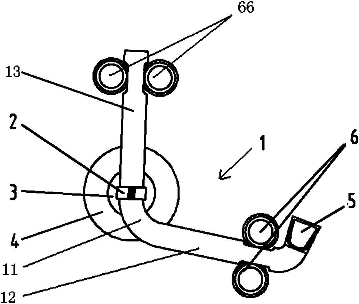
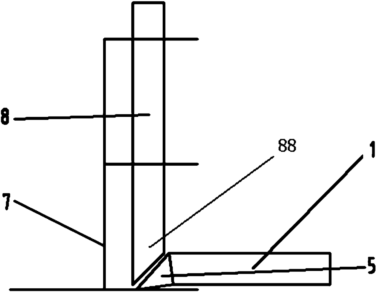
[0031] Such as Figure 1 to Figure 4 Shown. The invention discloses a rapid transfer device with adjustable drop point based on a rotary form, which includes a curved transfer channel 1, a driving mechanism that provides rotational power to the curved transfer channel 1, and a cargo supply mechanism that provides goods to the curved transfer channel 1;

[0032] The middle part of the curved transport channel 1 is a smoothly transitioned bend section 11, with the bend section 11 as a boundary, it is divided into a front section tube body 12 and a rear section tube body 13; the end of the front section tube body 12 is provided with an elbow Incoming port 5, the tail of the rear pipe body 13 is the outgoing port;

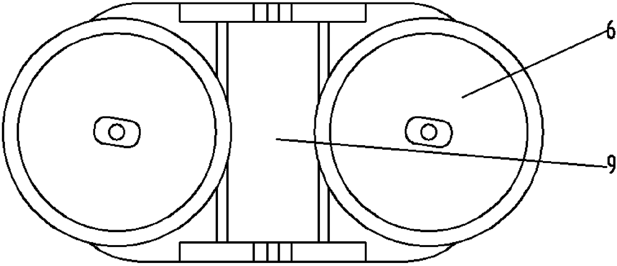
[0033] The front tube body 12 is provided with a first friction wheel set 6 symmetrically on both sides of the lower tube body near the elbow inlet 5, and two symmetrical wheels are provided on both sides of the tube body corresponding to the first friction wheel set 6 Th...


PUM


Abstract

The invention discloses an adjustable-drop-point type rapid transferring device and method based on a rotation form. The adjustable-drop-point type rapid transferring device based on the rotation form comprises a bent transferring channel, a driving mechanism of the bent transferring channel and a goods supplying mechanism supplying goods to the bent transferring channel. The middle portion of the bent transferring channel is a bent section in smooth transition, and the bent transferring channel is divided into a front pipe body section and a back pipe body section by the bent section. The front pipe body section is provided with an elbow goods inlet, and the back pipe body section is provided with a goods outlet. The front pipe body section and the back pipe body section are each provided with a friction wheel set. When the elbow goods inlet runs to the position below the goods supplying mechanism and shovels the goods, under the rotation inertia force of the bent transferring channel, the goods slides to the rotating friction wheel sets to be accelerated and then is thrown to a preset position. The technological means of the adjustable-drop-point type rapid transferring device based on the rotation form is simple and convenient and easy to perform, operation is convenient, and work efficiency is high; and the adjustable-drop-point type rapid transferring device based on the rotation form can continuously, rapidly and accurately throw the goods to the preset position, greatly shortens the production cycle and lowers the operating cost of logistics.

Description

Technical field [0001] The invention relates to logistics transfer equipment, in particular to a fast transfer device and method with adjustable drop points based on a rotary form. Background technique [0002] With the rise and rapid development of smart factories, modern factories have basically realized unmanned operation, which requires more complicated electromechanical structure assembly lines to complete various processes that can only be completed manually before; especially in terms of logistics transfer, goods are The requirements for transfer between places are not uncommon, so many transfer machines have been born, but most of them use the movement of tandem manipulators to achieve the purpose of transfer, but there are also many problems, such as the inability to transport long distances, etc. . [0003] Products in a factory are often completed through multiple processes, so each process may need to be carried out in different places. At this time, goods need to be t...

Claims


Application Information

Patent Timeline
Patent Type & Authority Patents(China)
IPC IPC(8): B65G47/94
CPCB65G47/94B65G2201/02
Inventor 张东王雨浓印智阳钟凯帆姚粤汉吴优曾繁源
Owner SOUTH CHINA UNIV OF TECH
Why Eureka
Try Eureka