
Model Boundary Generation Method and Device

A technology for generating devices and models, applied in the field of software, can solve problems such as efficiency constraints, and achieve the effect of efficient model stroke effects

Active Publication Date: 2019-12-03
FUJIAN TQ DIGITAL
View PDF2 Cites 0 Cited by
  • Summary
  • Abstract
  • Description
  • Claims
  • Application Information

AI Technical Summary

Problems solved by technology

[0005] Due to the constraints of hardware performance, it is difficult to use the post-processing scheme of the screen space to stroke the model on the mobile platform, and the efficiency is restricted to a certain extent.

Method used


Image

  • Model Boundary Generation Method and Device
  • Model Boundary Generation Method and Device

Examples


Embodiment Construction

[0042] In order to explain in detail the technical content, structural features, achieved goals and effects of the technical solution, the following will be described in detail in conjunction with specific embodiments and accompanying drawings.

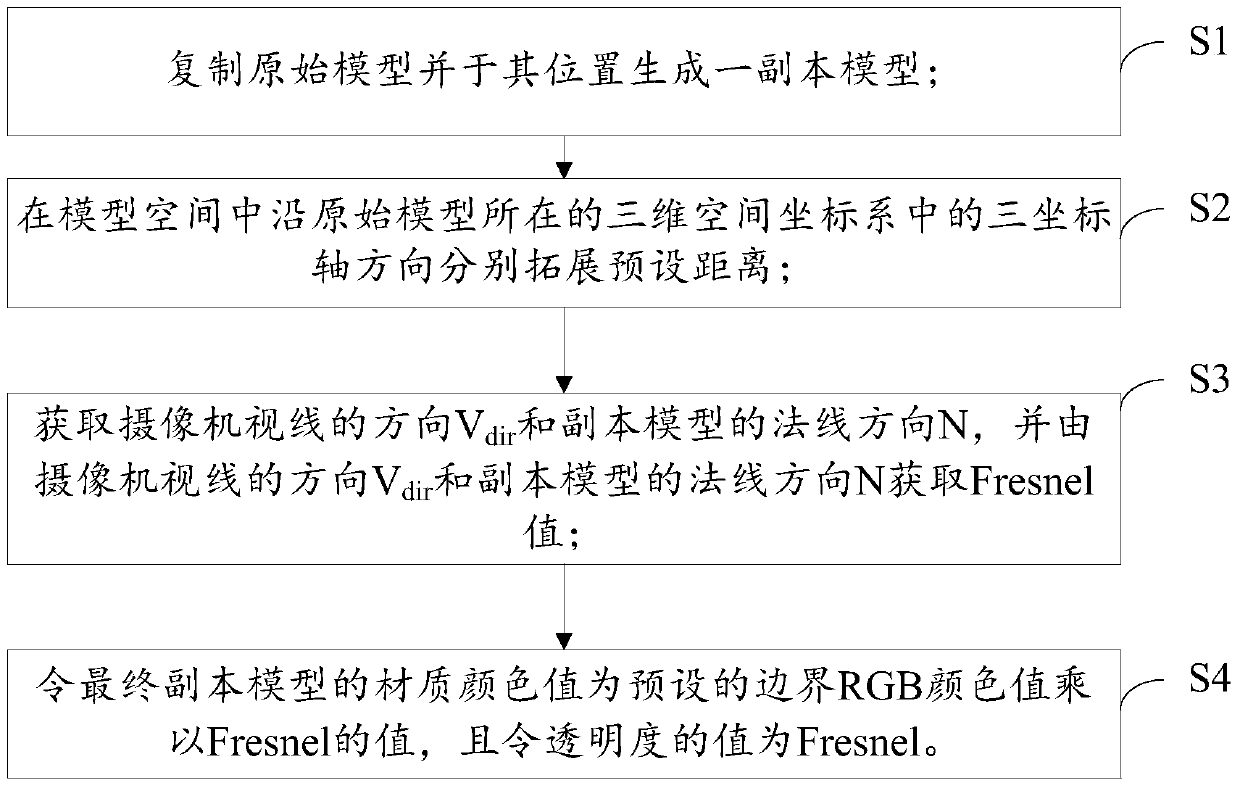
[0043] see figure 1 , is a flowchart of a method for generating model boundaries according to an embodiment of the present invention; the method includes the following steps:

[0044] S1. Copy the original model and generate a copy model in its place;

[0045] S2. In the model space, extend the preset distance along the directions of the three coordinate axes in the three-dimensional space coordinate system where the original model is located;

[0046] S3. Obtain the direction V of the camera line of sight dir and the normal direction N of the replica model, and by the direction V of the camera line of sight dir Get the Fresnel value with the normal direction N of the copy model;

[0047] S4. Make the material color value of the f...


PUM


Abstract

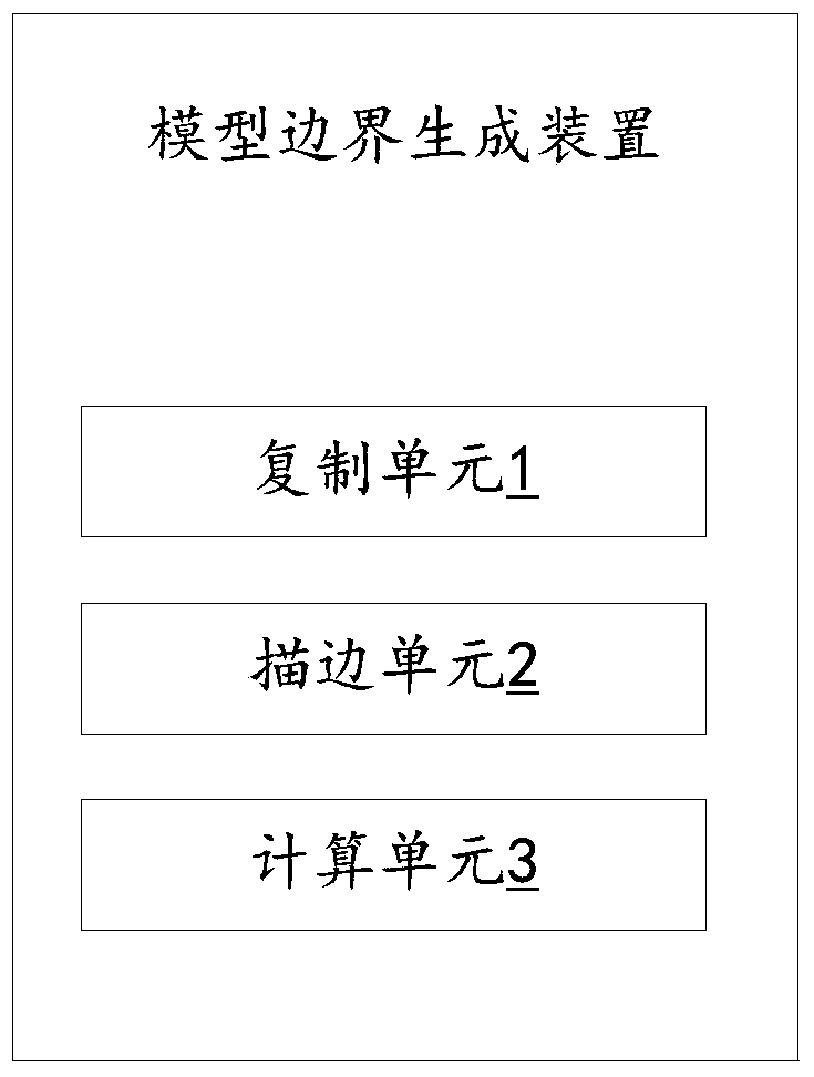
The invention provides a model boundary generation scheme which is simple, effective and wide in application ranges and can be used for mobile equipment. The method provided by the invention comprises the following steps: copying an original model, and generating a copy model on the position of the original model; independently expanding a preset distance along the three-coordinate-axis direction in a three-dimensional space coordinate system where the original model is positioned in a model space; obtaining the direction Vdir of a camera sight line and the normal direction N of a copy model, and obtaining a Fresnel value by the direction Vdir of the camera sight line and the normal direction N of the copy model; and causing the material color value of a final copy model to be a value obtained in way that a preset boundary RGB (Red, Green and Blue) color value is multiplied by Fresnel, and causing the value of transparency to be Fresnel. The invention simultaneously provides a device for realizing the above method, and the device can utilize a method capable of carrying out amplification by the model to generate a boundary and a method for carrying out edge coloring by a tinter to realize a quick and efficient model stroking effect.

Description

technical field [0001] The invention relates to the field of software, in particular to a method and device for generating model boundaries for game engine calculation. Background technique [0002] The mainstream technical methods for stroking models in the prior art mainly include: [0003] 1. A scheme for strokes based on screen space post-processing. The disadvantage of this solution is its low performance on mobile devices. [0004] 2. Use the vertex shader to expand the stroke in the normal direction. The problem with this scheme is that it is only suitable for models with uniform transition of normals in parts. [0005] Due to the constraints of hardware performance, it is difficult to use the screen space post-processing scheme to stroke the model on the mobile platform, and the efficiency is restricted to a certain extent. Contents of the invention [0006] Therefore, it is necessary to provide a method and device for generating model boundaries that are simpl...

Claims


Application Information

Patent Timeline
Patent Type & Authority Patents(China)
IPC IPC(8): G06F8/20G06T17/00
CPCG06F8/20G06T17/00
Inventor 吴拥民何汉鑫许凯杰刘德建陈宏展
Owner FUJIAN TQ DIGITAL
Learn More