Supercharge Your Innovation With Domain-Expert AI Agents!

An electromagnetic gas valve capable of slowing down and quick deflation

An electromagnetic gas valve, fast technology, applied in the direction of valve lift, valve details, valve device, etc., can solve the problems of poor use effect and difficult access of the inflation and deflation structure, achieve good air tightness, reduce the deflation speed, and avoid instant opening effect

Active Publication Date: 2018-06-22
XIAMEN CONJOIN ELECTRONICS TECH
View PDF5 Cites 0 Cited by
  • Summary
  • Abstract
  • Description
  • Claims
  • Application Information

AI Technical Summary

Problems solved by technology

[0004] The above-mentioned electromagnetic gas valve also has the following disadvantages: for the inflatable structure that needs to be inflated and deflated, the inflation and deflation speed of this type of electromagnetic gas valve is relatively fast. Therefore, some airbag structures need to deflate slowly to achieve better results. For example, the airbag of a sphygmomanometer requires a slow deflation speed so that the sphygmomanometer can have sufficient measurement time during the deflation phase. The traditional electromagnetic valve It is difficult to meet the above requirements due to the fast deflation speed

Method used


Image

  • An electromagnetic gas valve capable of slowing down and quick deflation
  • An electromagnetic gas valve capable of slowing down and quick deflation
  • An electromagnetic gas valve capable of slowing down and quick deflation

Examples


Embodiment Construction

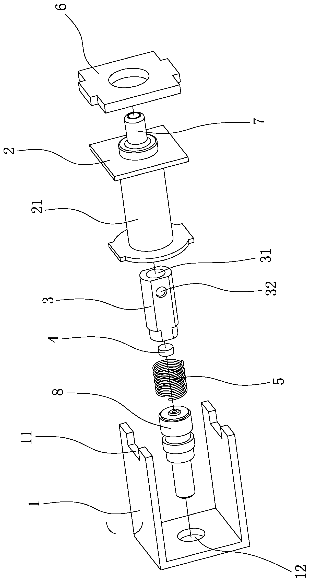
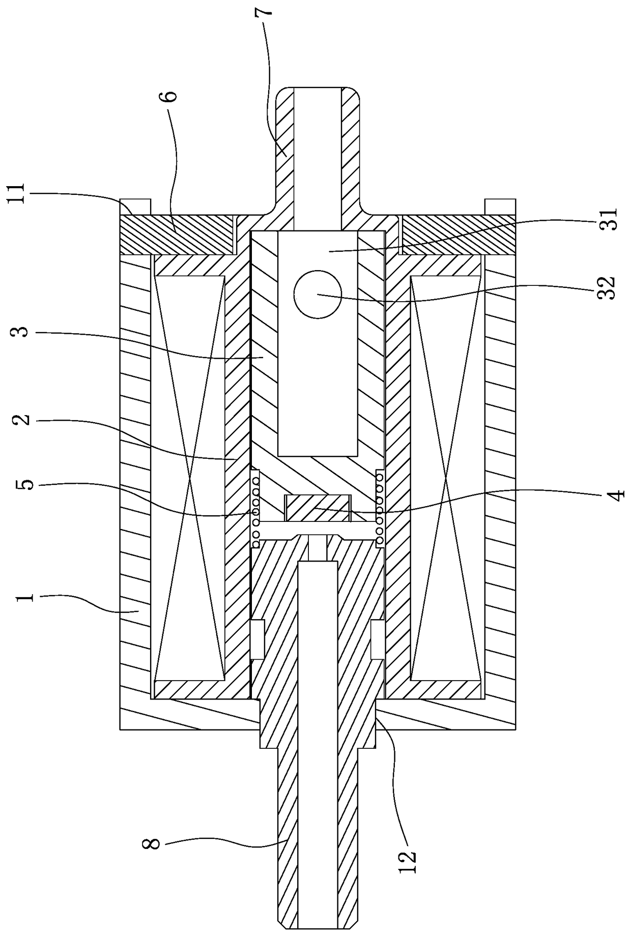
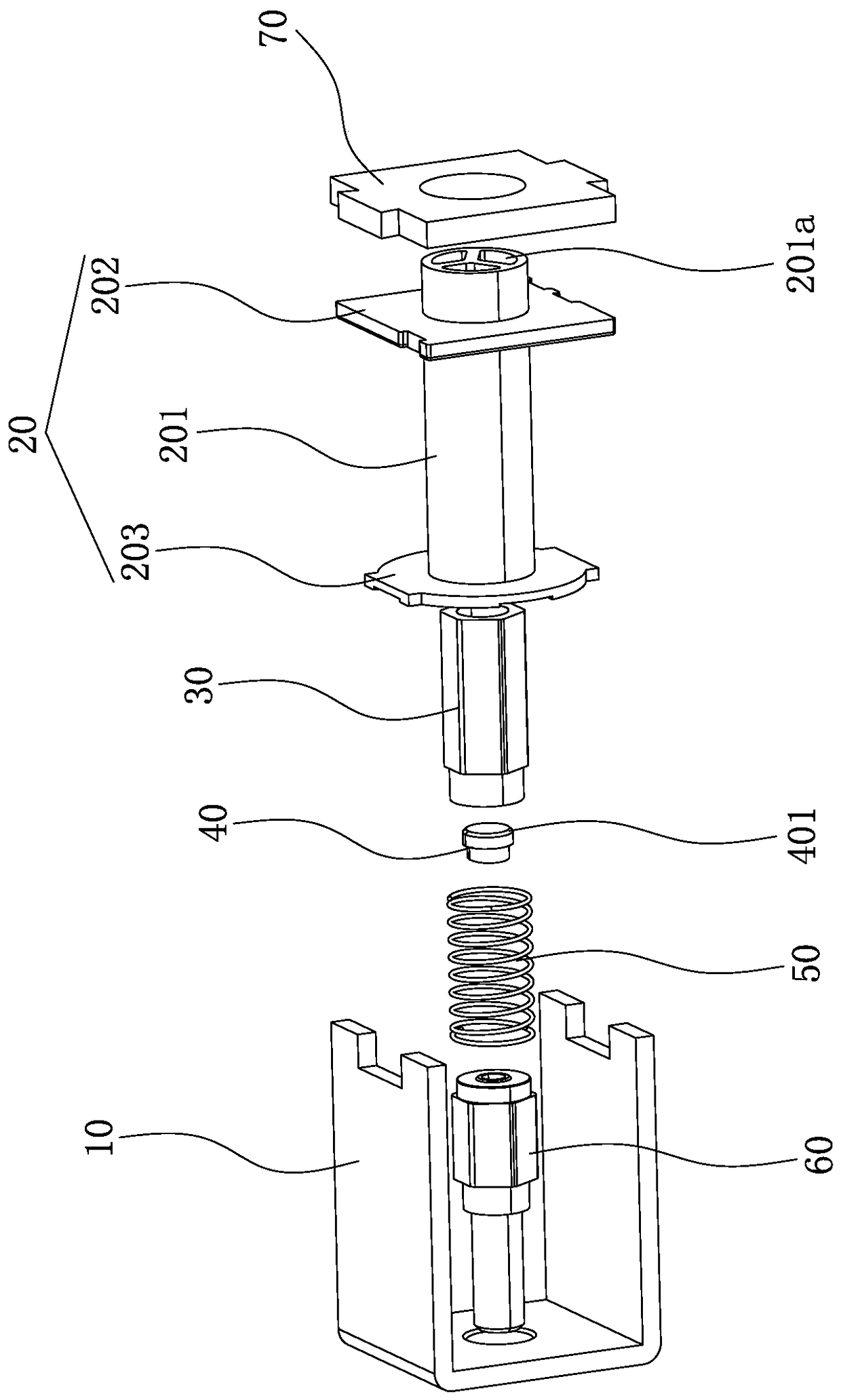
[0033] Such as Figure 3-4 As shown, a slow and fast deflated electromagnetic valve disclosed by the present invention includes a housing 10, a bobbin 20, a valve core 30, a rubber plug 40, a spring 50, an air outlet pipe 60 and a rear cover 70;

[0034] The bobbin frame 20 is composed of a central tube 201, a front baffle 201 and a rear baffle 203. The front baffle 202 and the rear baffle 203 are respectively sleeved on the front end and the rear end of the central tube 201, and the head of the central tube 201 forms an in-and-out stomata 201a;

[0035] Both the spool 30 and the outlet pipe 60 are magnetizable components, the spool 30 has a central through hole 301, the spool 30 and the spring 50 are assembled in the central tube 201 of the bobbin in an axially movable manner, and the valve The central through hole 301 of the core 30 communicates with the air inlet and outlet holes 201a of the central tube 201;

[0036] The front end of the air outlet pipe 60 extends into t...


PUM


Abstract

The invention discloses an electromagnetic air valve capable of exhausting air slowly and rapidly. The electromagnetic air valve capable of exhausting air slowly and rapidly comprises a shell, a reel, a valve element, a rubber plug cock, a spring, an air outlet pipe and a back cover. The reel is composed of a central pipe, a front baffle and a back baffle. The head of the central pipe is provided with air inlet and outlet holes. The valve element and the air outlet pipe are both components capable of being magnetized. The valve element is provided with a central through hole. The valve element and the spring are assembled in the central pipe of the reel in an axially movable manner. The front end of the air outlet pipe extends into the central pipe, and the back end of the air outlet pipe is fixed to the shell. One end of the spring abuts against the valve element, and the other end of the spring abuts against the air outlet pipe. One end of the rubber plug cock abuts against the air outlet pipe, and the other end of the rubber plug cock corresponds to the central through hole of the valve element. Besides, the rubber plug cock can come into or disengage from the central through hole. The periphery of the side, corresponding to the central through hole, of the rubber plug cock forms a slope. The back cover is buckled to the rear end of the shell. The electromagnetic air valve can slowly and rapidly reduce the air exhaust speed, the air exhaust stage is prolonged through slow air exhaust, and meanwhile the rapid air exhaust function is also kept.

Description

technical field [0001] The invention relates to an electromagnetic gas valve, in particular to an electromagnetic gas valve capable of slowing down and quick deflation. Background technique [0002] In the existing technology, such as Figure 1-2 An electromagnetic air valve shown includes a casing 1, a bobbin 2, a valve core 3, a rubber plug 4, a spring 5, a rear cover 6, an axial air inlet pipe 7 and an axial air outlet pipe 8, wherein the rubber plug The nozzle 4 is fixed on the front end of the valve core 3, and the rear end of the valve core 3 is provided with an air guide hole, the air guide hole is formed by a combination of a central air hole 31 and an axial air hole 32, and the valve core 3 and the spring 5 are assembled around the In the central tube 21 of the bobbin frame 2, the axial air inlet pipe 7 and the axial air outlet pipe are fixed on the rear end and the front end of the bobbin frame in 8 and a half parts, and the valve core 3 and the axial air outlet pi...

Claims


Application Information

Patent Timeline
Patent Type & Authority Patents(China)
IPC IPC(8): F16K31/06F16K1/00
CPCF16K1/00F16K31/0655F16K31/0675
Inventor 颜宏
Owner XIAMEN CONJOIN ELECTRONICS TECH
Features
  • R&D
  • Intellectual Property
  • Life Sciences
  • Materials
  • Tech Scout
  • Unparalleled Data Quality
  • Higher Quality Content
  • 60% Fewer Hallucinations
Learn More