
Anti-theft device for portable computers

a portable computer and anti-theft technology, applied in the direction of locking devices, locking applications, transportation and packaging, etc., can solve the problems of inconvenient routine engagement of the device, and inability to fully realize the effect of the devi

Inactive Publication Date: 2006-04-18
AVGANIM MAIR
View PDF14 Cites 54 Cited by
  • Summary
  • Abstract
  • Description
  • Claims
  • Application Information

AI Technical Summary

Benefits of technology

[0013]Thus provided according to the invention is an anti-theft device for portable computers having a base casing and a hingeable cover, one wall of the base casing being formed with a dedicated slot, the device being of a generally U-shape having two legs and a web portion, the distance between the legs being slightly greater than the thickness of the portable computer in the closed position therof, and comprising a rotatable locking mechanism installed within the web portion, drivingly coupled to a T-shaped tip adapted to be inserted into the slot in one position of the mechanism and, by rotating the mechanism by less than 180°, the tip becoming locked within the base casing while the legs extend one underlying the bottom surface of the base casing and the other overlying the top surface of the hingeable cover, thus preventing the opening of the cover, and means for securing the device to a stationary object.

Problems solved by technology

Since the use of portable computers has gained vast popularity during recent years, the problem of their theft became more and more severe.
These prior art devices mainly suffered the following disadvantages:(a) The pin insertion and withdrawal mechanism was inherently complicated and therefore costly;(b) The routine of engaging the device was inconvenient; and(c) The device was easily vulnerable to being forced open.

Method used


Image

  • Anti-theft device for portable computers
  • Anti-theft device for portable computers
  • Anti-theft device for portable computers

Examples


Embodiment Construction

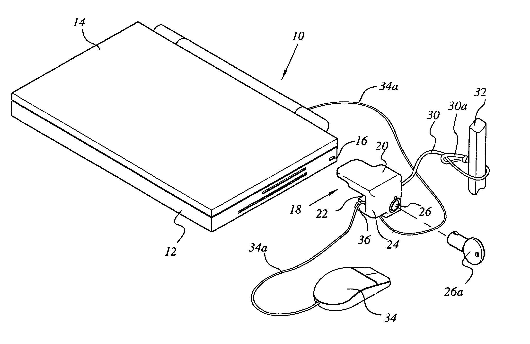
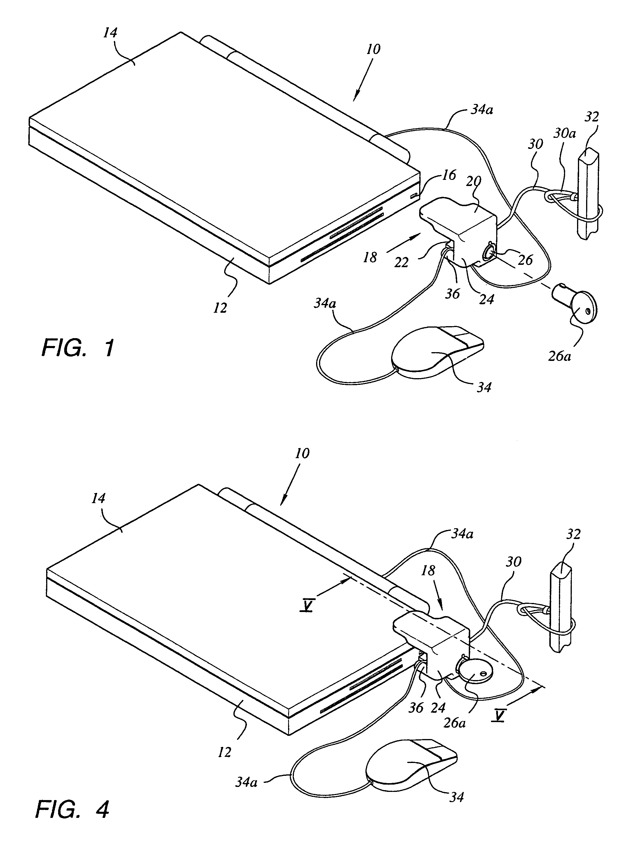
[0027]In FIG. 1 there is shown a portable computer 10 having a base casing 12 and a hingeable cover 14 which usually accommodates the computer screen.

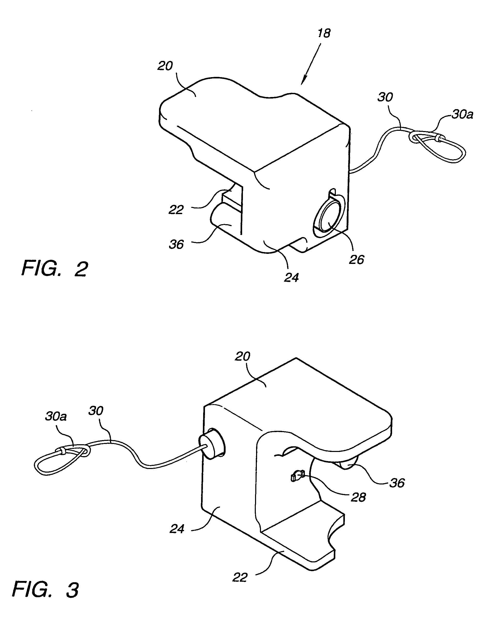
[0028]As already mentioned, a standardized dedicated slot 16 is formed at one of the base casing walls, as shown, adapted to be engaged by anti-theft device 18. The device 18 is generally U-shaped (see FIGS. 2 and 3), comprising a top leg 20, a bottom leg 22 and a bridging web portion 24.

[0029]The distance or gap between the legs 20 and 22 depends on the total thickness of the computer when closed, and therefore various sized devices will have to be available on the market in order to accommodate the different computer models.

[0030]A key-operated rotatable (cylinder or other type) locking mechanism 26, with key 26a is included for revolving T-shaped tip 28 (see FIGS. 5 and 6) insertable into and rotatable within the dedicated slot 16.

[0031]A steel cable 30 with loop 30a is provided as best seen in FIG. 3.

[0032]The locking engagement of...


PUM


Abstract

An anti-theft device (10) for portable computers having a base casing (12) and a hingeable cover (14). One wall of the base casing (14) is formed with a dedicated slot (16). The device (10) is generally U-shaped, having two legs (20; 22), and a web portion (24). The device (10) comprises a rotatable locking mechanism (26) installed within the web portion (24), drivingly coupled to a T-shaped tip (28) adapted to be inserted into the slot (16) in one position of the mechanism and, by rotating the mechanism by less than 180°, the tip (28) becomes locked within the base casing (12) while the legs (20; 22) extend one (22) underlying the bottom surface of the base casing (12) and the other (20) overlying the top surface of the hingeable cover (14), thus preventing the opening of the cover. A cable is used for securing the device (10) to a stationary object (32).

Description

[0001]The present patent application is a non-provisional application of International Application No. PCT / IL02 / 00927, filed Nov. 21, 2002.BACKGROUND OF THE INVENTION[0002]Since the use of portable computers has gained vast popularity during recent years, the problem of their theft became more and more severe. Unattended computers in university libraries, offices and even restaurants are “snatched” within seconds.[0003]Various methods and means have been proposed to solve this problem. The most widespread method presently used is to secure a locking device against a standardized dedicated slot formed (by the manufacturers) at one of the plastic made walls of the computer casing. A steel cable, extending from the locking device is tied to a stationary body such as around a table leg.[0004]Among the locking devices that were developed to implement this method are those disclosed in U.S. Pat. Nos. 5,327,752; 5,447,044; 5,579,657; 6,006,557 and the inventor's U.S. Pat. No. 6,244,082.[00...

Claims


Application Information

Patent Timeline
Patent Type & Authority Patents(United States)
IPC IPC(8): E05B73/00
CPCE05B73/0082E05B73/0005Y10T70/5544Y10T70/5566Y10T70/409Y10T70/5009
Inventor AVGANIM, MAIR
Owner AVGANIM MAIR
Learn More