
Self-pressurized valve group

A self-pressurization, valve group technology, applied in valve details, valve devices, valve operation/release devices, etc., can solve problems such as high cost

Active Publication Date: 2018-06-26
SUZHOU KEDI FLUID CONTROL EQUIP
View PDF5 Cites 0 Cited by
  • Summary
  • Abstract
  • Description
  • Claims
  • Application Information

AI Technical Summary

Problems solved by technology

In real life, people often need to use higher water pressure to pass water to a higher position, or to make water pipes spray higher water flow. The traditional way is to use water pumps to complete the addition of water. Pressurization, this pressurization method needs to consume a large amount of electricity to complete

Method used


Image

  • Self-pressurized valve group
  • Self-pressurized valve group

Examples


Embodiment Construction

[0013] Below in conjunction with embodiment the present invention is further described:

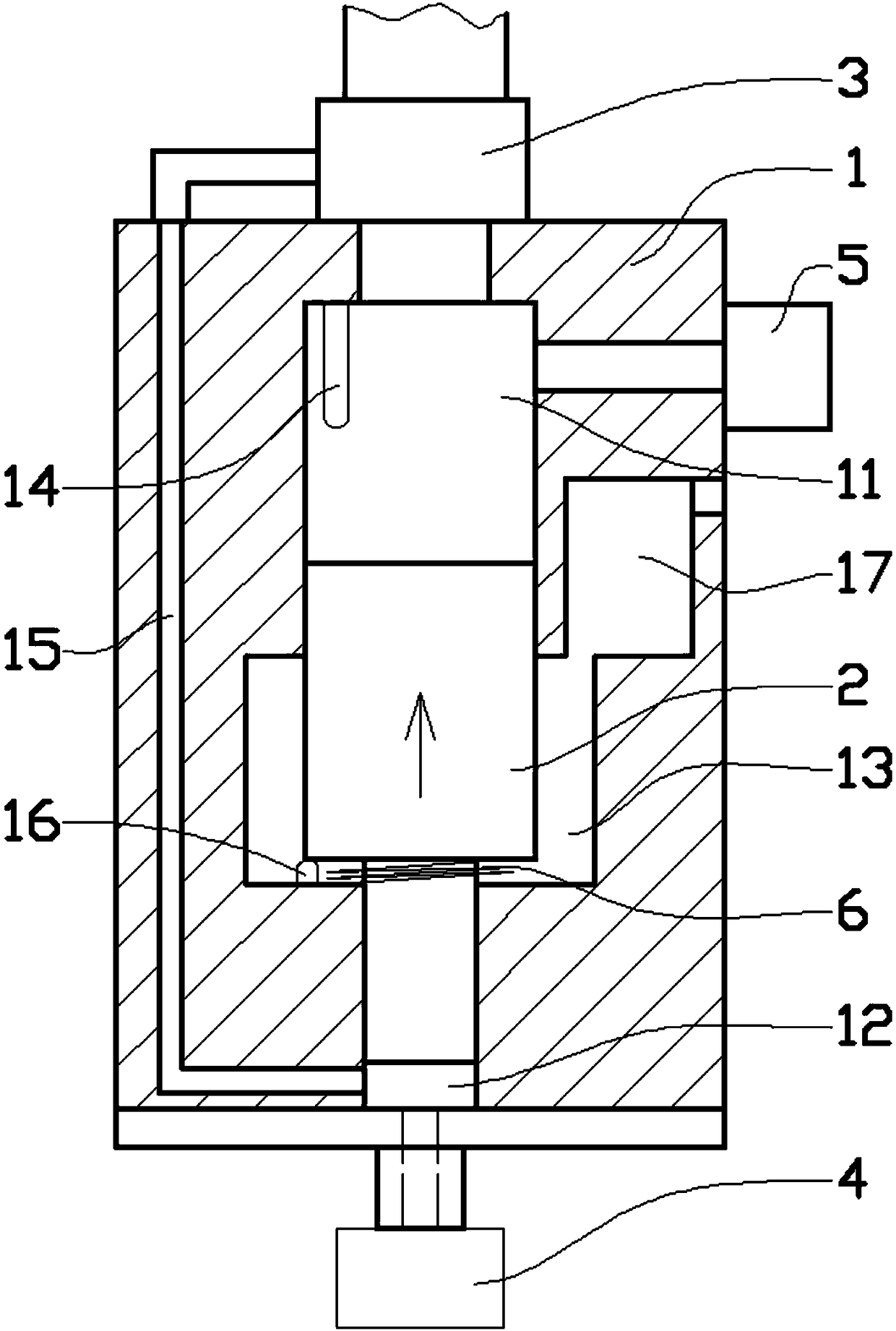
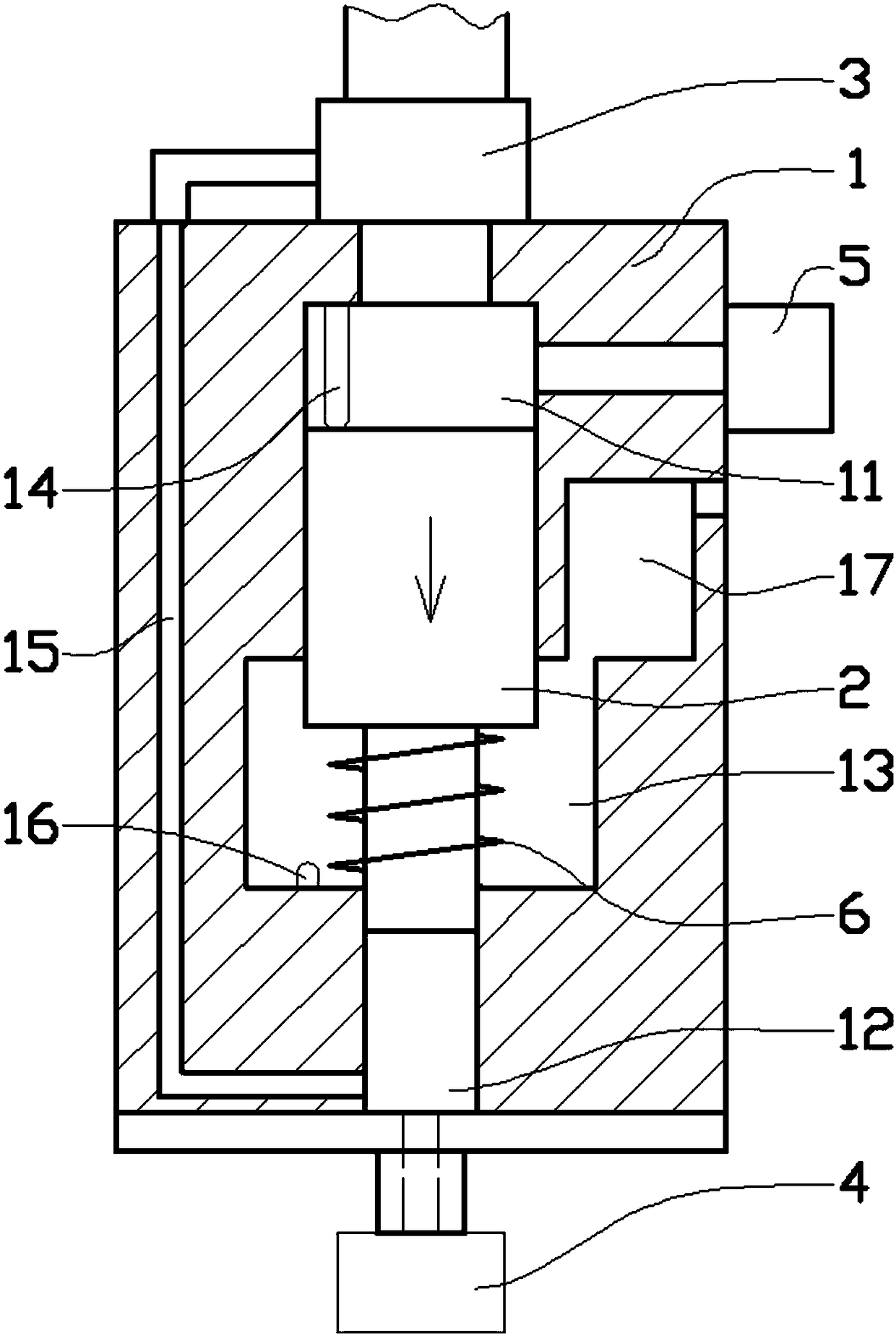
[0014] Such as figure 1 , figure 2 As shown in the embodiment, the self-pressurizing valve group includes a main valve body 1 and a pressure block 2, and the main valve body 1 is designed with a vertically coaxial cylindrical upper pressure chamber 11 and a lower pressure chamber 12. , the diameter of the upper pressure chamber 11 is larger than that of the lower pressure chamber 12, an adjustment chamber 13 with a diameter larger than that of the upper pressure chamber 11 is designed between the upper pressure chamber 11 and the lower pressure chamber 12, and the pressure block 2 is composed of two sections with different diameters Composed of coaxial cylinders, the upper cylinder of the pressure block 2 is slidingly and sealingly assembled in the upper pressure chamber 11, and the lower cylinder of the pressure block 2 is slidingly and sealingly assembled in the lower pressure chamber...


PUM


Abstract

The invention provides a self-pressurizing type valve group comprising a main valve body and a pressure block. The inside of the main valve body is provided with an upper pressure cavity and a lower pressure cavity which are cylindrical in shape and are arranged vertically and coaxially; the diameter of the upper pressure cavity is greater than that of the lower pressure cavity; an upper pillar body of the pressure block is mounted in the upper pressure cavity in a sliding seal manner and a lower pillar body of the pressure block is mounted in the lower pressure cavity in a sliding seal manner; the lower portion of the lower pressure cavity communicates with a water outlet valve; the upper portion of the upper pressure cavity is connected with a water inlet pipe via a water inlet valve; the water inlet valve is a three-way valve; the lower portion of the lower pressure cavity communicates with the water inlet valve; the upper portion of the upper pressure cavity communicates with a water escape valve. When the valve group is used, a pressurizing function can be fulfilled based on the pressure of a water body and the gravity of the pressure block owing to the different diameters of the upper portion and the lower portion of the pressure block, so that the valve group is more energy-saving in use.

Description

technical field [0001] The invention relates to the technical field of valves, in particular to a self-pressurizing valve group. Background technique [0002] The valve is a control component in the fluid delivery system, which has functions such as cut-off, adjustment, flow diversion, reverse flow prevention, pressure stabilization, flow diversion or overflow pressure relief. Valves used in fluid control systems range from the simplest cut-off valves to various valves used in extremely complex automatic control systems, with a wide variety of varieties and specifications. These valves pass the fluid into the valve body, and control the fluid channel in the valve body through the valve core to complete the on-off control of the fluid. In this control process, due to the resistance of the valve body channel, when the fluid enters the valve The pressure usually decreases. In real life, people often need to use higher water pressure, so that the water can be passed to a highe...

Claims


Application Information

Patent Timeline
Patent Type & Authority Patents(China)
IPC IPC(8): F16K31/363
CPCF16K31/363
Inventor 田洪卫
Owner SUZHOU KEDI FLUID CONTROL EQUIP
Learn More