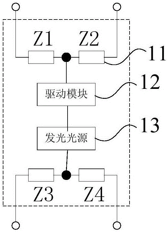
Simulation filament impedance circuit, LED lamp tube, and LED illuminating system

A technology of LED lamp tube and LED lighting, which is applied in the field of lighting and can solve problems affecting the conversion efficiency of lamp tubes

Active Publication Date: 2016-11-09
OPPLE LIGHTING
View PDF10 Cites 5 Cited by
  • Summary
  • Abstract
  • Description
  • Claims
  • Application Information

AI Technical Summary

Problems solved by technology

[0011] Therefore, no analog filament impedance circuit has been proposed so far that can meet the IEC standard test without affecting the conversion efficiency of the lamp tube.

Method used


Image

  • Simulation filament impedance circuit, LED lamp tube, and LED illuminating system
  • Simulation filament impedance circuit, LED lamp tube, and LED illuminating system
  • Simulation filament impedance circuit, LED lamp tube, and LED illuminating system

Examples


Embodiment 1

[0045] Figure 4 A schematic structural diagram of a circuit for simulating filament impedance according to an embodiment of the present invention is shown. see Figure 4 , the simulated filament impedance circuit includes a first resistor 41 , a second resistor 42 and a first capacitor 43 , where the first resistor 41 and the first capacitor 43 are connected in parallel and then connected in series with the second resistor 42 .

[0046] Figure 4 The expression of the equivalent impedance value Z of the simulated filament impedance circuit shown is:

[0047] Z = R 1 × 1 j w C R 1 + 1 j w C + ...

Embodiment 2

[0059] Figure 5 A schematic structural diagram of a circuit for simulating filament impedance according to an embodiment of the present invention is shown. see Figure 5 , the simulated filament impedance circuit includes a first resistor 51 , a second resistor 52 and a first capacitor 53 , wherein the first resistor 51 and the first capacitor 53 are connected in series and then connected in parallel with the second resistor 52 .

[0060] Figure 5 The expression of the equivalent impedance value Z of the simulated filament impedance circuit shown is:

[0061] Z = ( R 1 + 1 j w C ) × R 2 R 1 + 1 j ...


PUM


Abstract

The invention provides a simulation filament impedance circuit, an LED lamp tube, and an LED illuminating system. The simulation filament impedance circuit has pole frequency and zero frequency. The pole frequency is smaller than the zero frequency. When input frequency is smaller than the pole frequency, the equivalent impedance value of the simulation filament impedance circuit remains unchanged, and is a first equivalent impedance value. When the input frequency is greater than the pole frequency and smaller than the zero frequency, the equivalent impedance value of the simulation filament impedance circuit is lowered along with the rising of the input frequency. When the input frequency is greater than the zero frequency, the equivalent impedance value of the simulation filament impedance circuit remains unchanged, and is a second equivalent impedance value. The first equivalent impedance value is greater than the second equivalent impedance value. By adopting the simulation filament impedance circuit provided by the invention, requirements of IEC standard tests are satisfied, and the conversion efficiency of the lamp tube is not affected.

Description

technical field [0001] The invention relates to the lighting field, in particular to an analog filament impedance circuit, an LED lamp tube and an LED lighting system. Background technique [0002] Light Emitting Diode (LED for short) light source has been widely concerned and applied due to its advantages of small size, high brightness, low power consumption and long service life. a trend. [0003] Traditional fluorescent lamps cannot be directly connected to the mains to work, and a ballast needs to be added between the mains and the traditional fluorescent lamps. According to different operating frequencies, ballasts mainly include magnetic ballasts and electronic ballasts. Among them, magnetic ballasts output low-frequency voltage and low-frequency current, generally at 50 / 60Hz, and electronic ballasts output high Frequency voltage and high frequency current, generally above 20kHz. In the prior art, the method of replacing traditional fluorescent lamps with LED lamps ...

Claims


Application Information

Patent Timeline
Patent Type & Authority Applications(China)
IPC IPC(8): H05B33/08F21K9/278F21V23/00F21Y115/10H05B44/00
CPCF21V23/003H05B45/00
Inventor 文威
Owner OPPLE LIGHTING
Why Eureka
Try Eureka