
Solution pump system

一种溶液、溶液腔的技术,应用在溶液泵领域,能够解决不能充分起作用等问题

Active Publication Date: 2016-11-09
ROCKY RES INC
View PDF9 Cites 4 Cited by
  • Summary
  • Abstract
  • Description
  • Claims
  • Application Information

AI Technical Summary

Problems solved by technology

Therefore, hydraulic diaphragm pumps of the type currently in use will not function adequately if there is no fluid in the solution chamber at start-up

Method used


Image

  • Solution pump system
  • Solution pump system
  • Solution pump system

Examples


Embodiment Construction

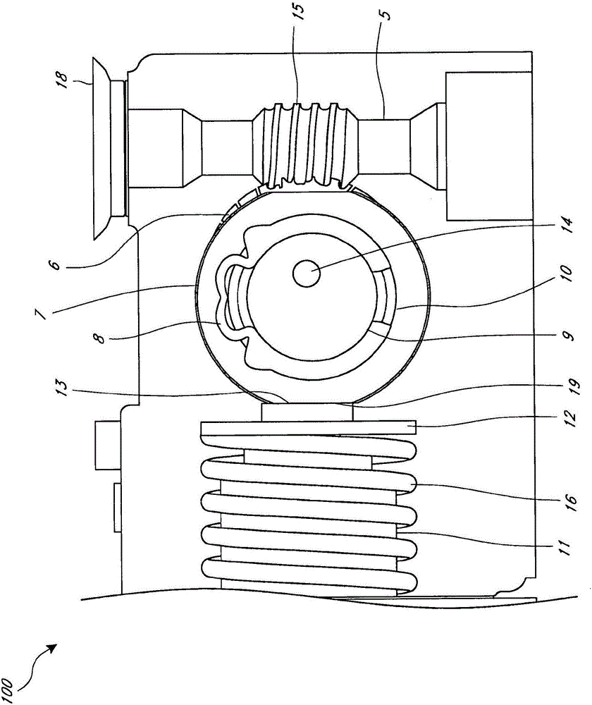
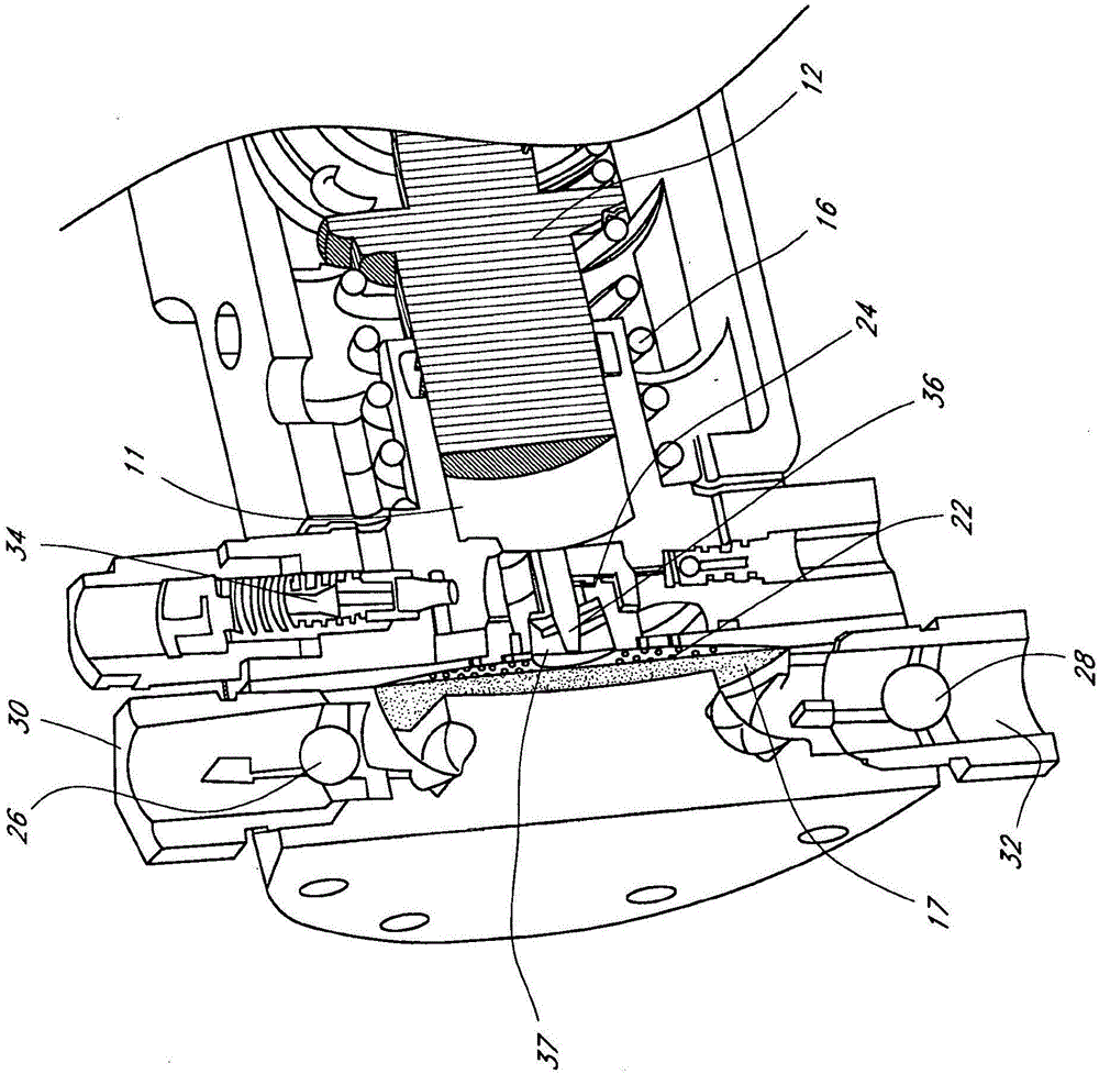
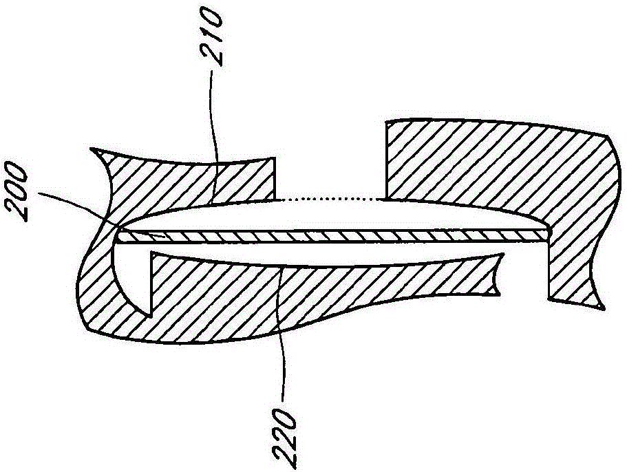
[0018] Embodiments relate to solution pumps capable of self-priming through an access tube. In some embodiments, the solution pump is a plunger driven hydraulic diaphragm solution pump having a solution chamber. In this embodiment, the membrane substantially conforms to the concave inner surface of the solution chamber. By substantially conforming to the interior surface of the solution chamber, the solution pump is able to pump vapor for an extended period of time until solution is drawn into the solution chamber. In addition, the concave inner surface of the solution chamber may include steps or ridges formed along the outer peripheral surface and limit the outer periphery of the surface adjacent to the inlet port and the outlet port. The step can help prevent deformation of the diaphragm due to the inlet and outlet ports formed in the solution chamber wall.

[0019] In this way, the step helps prevent the diaphragm from entering the inlet or outlet and deforming or bulgin...


PUM


Abstract

A plunger driven solution pump is described that is configured to have a diaphragm that substantially conforms to the volume of a pump solution chamber when in a fully outwardly deflected state. The solution chamber may have an inlet port and an outlet port form in a concave solution chamber wall. A step, or ridge, may be formed along an outer periphery of the solution chamber wall and adjacent the inlet and outlet ports to prevent the diaphragm from becoming deformed from pressure against the solution chamber wall. This configuration may allow the pump to efficiently self-prime.

Description

technical field [0001] Embodiments relate to diaphragm-based solution pumps for moving liquids. More specifically, embodiments relate to solution pumps configured to self-prime for refrigeration systems. Background technique [0002] Many different types of systems rely on solution pumps to move liquid from one part of the device to another. For example, liquid / vapor absorption systems typically use an absorber heat exchange cycle or a generator / absorber heat exchange (GAX) cycle for cooling and heating indoor coils and other heat exchange exposed to the space or load to be conditioned element. In these types of installations, a solution pump is typically used to pump the ammonia-rich absorption fluid from the absorber assembly to the generator assembly. This process maintains a pressure differential between the low pressure on the absorber side and the high pressure on the generator side of the absorption system plant. An example of an ammonia water absorption heat pump...

Claims


Application Information

Patent Timeline
Patent Type & Authority Applications(China)
IPC IPC(8): F04B43/067
CPCF04B43/067F04B45/0533
Inventor P·萨基西恩U·罗肯费勒
Owner ROCKY RES INC
Features
  • Generate Ideas
  • Intellectual Property
  • Life Sciences
  • Materials
  • Tech Scout
  • Unparalleled Data Quality
  • Higher Quality Content
  • 60% Fewer Hallucinations
Learn More