Turn-over device support

A bed frame and frame technology, applied in bed frames, medical science, hospital beds, etc., can solve problems such as lack of ventilation, complex structure, easy to break and unsafe

Inactive Publication Date: 2016-11-30
李俊彦
View PDF8 Cites 2 Cited by
  • Summary
  • Abstract
  • Description
  • Claims
  • Application Information

AI Technical Summary

Problems solved by technology

Some of these prior technologies have complex structures and are not easy to produce; some have a suspension structure above the patient to cause a sense of oppression; some must bind the hands and feet of the patient; some have no back ventilation; and some have unscientific str

Method used


Image

  • Turn-over device support
  • Turn-over device support
  • Turn-over device support

Examples


Embodiment 1

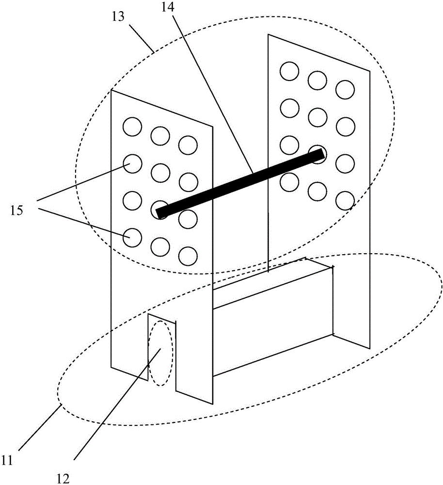
[0107] A stand for turning device, please refer to Figure 1-Figure 4 , Figure 7 .

[0108] Please refer to figure 1 , The first seating portion 11 and the first shaft portion 13, wherein the shape of the groove 12 of the first seating portion 11 is suitable to be erected on the edge of the bed frame 52, and the first shaft portion 13 is provided with many holes 15 for placing the rotating shaft 14 ;

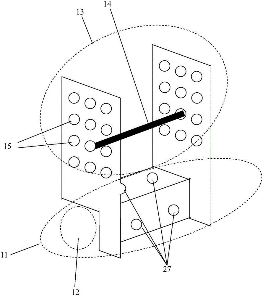
[0109] Also, please refer to figure 2 , The first seating portion 11 and the first shaft portion 13, wherein the groove 12 of the first seating portion 11 is shaped suitable to be erected on the bed 51 (the first seating portion 11 may be provided with screw holes 27 for fixing to the bed 51), and The first shaft portion 13 is provided with many holes 15 for placing the rotating shaft 14.

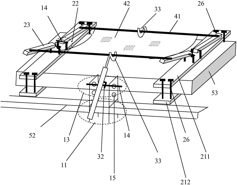
[0110] Again, please refer to image 3 or Figure 4 , The first placement part 11 of the stand of the turning device is erected on the edge of the bed frame 52 (please refer to image 3 ) Or in...

Embodiment 2

[0117] A stand for turning device, mainly including:

[0118] The first seating portion 11 is provided with a first shaft portion 13, and the first seating portion 11 can clamp the mattress 53, or can be fixed to the bed 51 or the bed frame 52; and

[0119] The first shaft portion 13 is provided with a rotating shaft 14 or any number of holes 15 or slots for placing the rotating shaft 14 to hang or connect a telescopic cylinder 31 to allow the telescopic cylinder 31 to rotate.

[0120] Although the first placement portion 11 of this embodiment can be erected on the bed frame 52 or the bed 51 without the groove 12, Figure 5 As shown, dividing the first seating portion 11 into an upper fixing plate 211 and a lower fixing plate 212 can clamp the mattress 53, and a first shaft portion 13 is set between the upper fixing plate 211 and the lower fixing plate 212, or as Image 6 As shown, the following fixing plate 212 is fixed to the bed 51 with screws 26 (the bed 51 and the screws are not ...

Embodiment 3

[0131] A stand for turning device, mainly including:

[0132] The first shaft portion 13 is provided in the second seating portion 21, and the first shaft portion 13 is provided with a rotating shaft 14 or any number of holes 15 or grooves for placing the rotating shaft 14 to hang or connect a telescopic cylinder 31, Make the telescopic cylinder 31 rotate;

[0133] The second seating portion 21 is provided with a first shaft portion 13 and a second shaft portion 22, and the second seating portion 21 can clamp the mattress 53 or can be fixed to the bed 51 or the bed frame 52;

[0134] The second shaft portion 22 is provided in the second seating portion 21, and the second shaft portion 22 is provided with a rotating shaft 14 or any number of holes 15 or grooves for placing the rotating shaft 14 to connect and support the short arm 23 to make it short The arm 23 can be rotated; and

[0135] The short arm 23 is connected with the flexible medium carrier and / or the side rod 41 or the rig...


PUM


Abstract

There are many patients in the hospital or at home or in long-term care centers who must often be assisted in turning over by caregivers. Not only are large human resources are occupied, an economic burden is caused for some employers. A great problem is that caregivers cannot get enough rest because of the need to regularly help patients turn over, especially at midnight. In the present invention, a turn-ove device support can be applied to a general bed or be clamped on a mattress, besides being applied to the bed, via the arrangement of a first arrangement part or a second arrangement part. Furthermore, via arrangmenet of a second shaft part, a short-arm and side-bars, smooth and stable operation of the turn-over device support is allowed.

Description

Technical field [0001] The bracket of the turning device of the present invention can be applied to a general bed or to clamp a mattress through the first placement part or the second placement part, and not only to the hospital bed; The establishment of the two-axis part, the short arm and the side bar can make the stand of the turning device operate more smoothly. The invention can be widely used in hospitals, homes or long-term care centers. Background technique [0002] Regarding the prior art, I have analyzed the existing types of turning devices in my previous work (2) of the Taiwanese New Patent No. M488987, a turning device, and most of them are nothing more than the following: (1) Manual turning assistance (2) Air cushion flip; (3) Use up and down linear motion to turn over; (4) Use bed turnover; (5) Use bed deformation; (6) Suspended flip; (7) Others. Some of these prior technologies are complicated in structure and not easy to produce; some are caused by the hanging ...

Claims


Application Information

Patent Timeline
IPC IPC(8): A47C21/00A47C19/00A47C21/08A61G7/057
CPCA61G7/057A47C21/00A47C19/00A47C21/08
Inventor 李俊彦
Owner 李俊彦
Why Eureka
Try Eureka