Pull force measurement tool
A technology of tension measurement and tools, applied in the direction of measuring devices, using stable tension/pressure testing material strength, instruments, etc., can solve the problems of high environmental requirements, large volume and quality, and difficult relocation, etc., to achieve structural Streamlined, easily portable, less demanding effects for the environment
- Summary
- Abstract
- Description
- Claims
- Application Information
AI Technical Summary
Problems solved by technology
Method used
Image
Examples
Embodiment 1
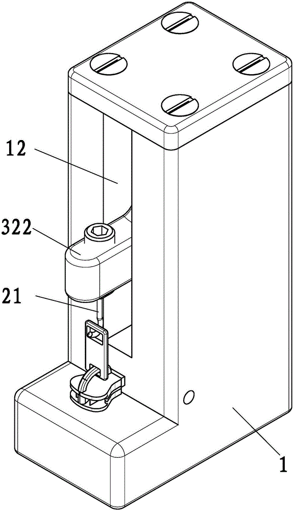
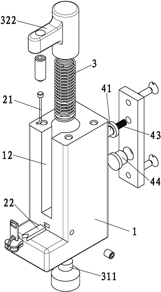
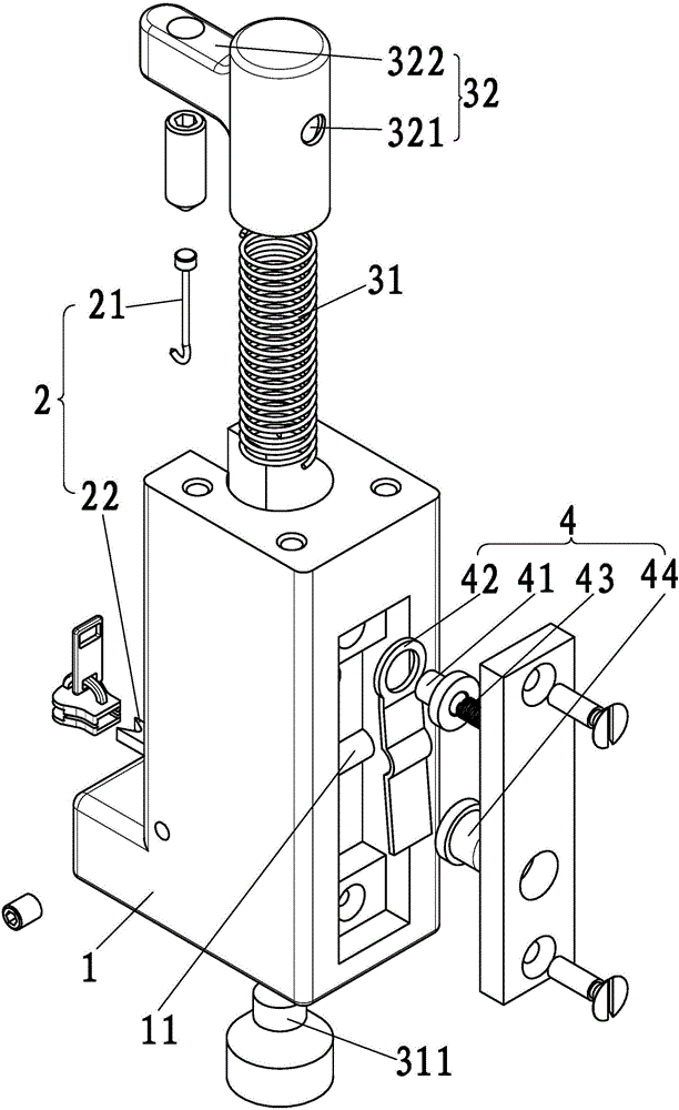
[0025] Such as Figure 1 to Figure 4 As shown, the tension measurement tool of the present invention, which can also be called a pull-pan measurement tool, mainly includes a pull positioning mechanism 2 , a force applying mechanism 3 and a switching mechanism 4 .
[0026] Preferably, the present invention also includes a body 1 , which is mainly used for installing the pull positioning mechanism 2 , the force applying mechanism 3 and the switching mechanism 4 .
[0027] The pull positioning mechanism 2 can pull the workpiece to be tested, and the workpiece to be tested will be described below with a zipper slider as an example. The pull positioning mechanism 2 mainly includes a first positioning portion 21 and a second positioning portion 22 which are arranged correspondingly. The corresponding ends of the first positioning portion 21 and the second positioning portion 22 are adapted to the pull position of the workpiece to be measured respectively. In short, the opposite end...
Embodiment 2
[0030] The force applying mechanism 3 mainly applies the opposing pulling force to the opposing pulling positioning mechanism 2 . The biasing mechanism 3 mainly includes a biasing spring 31 that can expand and contract freely. The elastic force generated by the two free ends of the biasing spring 31 can be applied to the first positioning portion 21 and the second positioning portion 22 correspondingly.
[0031] The biasing mechanism 3 includes a stretchable biasing spring 31 , and the two free ends of the biasing spring 31 directly or indirectly bear against the first positioning portion 21 and the second positioning portion 22 .
[0032] Preferably, the lower free end of the biasing spring 31 is disposed on the body 1 , or is sleeved on a spring pin 311 protruding from the body 1 . The upper free end of the biasing spring 31 is connected to the first positioning portion 21 through a cap 32 . Specifically, one end of the cap 32 is cap-shaped and sleeved on the upper free en...
Embodiment 3
[0035] The switching mechanism 4 mainly switches between the force application state and the force withdrawal state of the force application mechanism 3 . The switching mechanism 4 includes a limiting portion 41 , and the limiting portion 41 is movably connected to the force applying mechanism 3 in a detachable manner.
[0036] Preferably, the switching mechanism 4 further includes a pressing portion 44 , and the limiting portion 41 includes a limiting rod 42 and a limiting spring 43 . A limiting hole 321 is opened on the cap 32 . The pressing part 44 pushes against one end of the limit rod 42, and the other end of the limit rod 42 protrudes to set a limit part 41. The limit part 41 can adopt a structure such as a pin shape or a cap shape, and the limit part 41 passes through a limit spring. 43 can freely expand and contract in the limiting hole 321 . The limiting rod 42 is provided on the main body 1 in a swingable manner around the fulcrum 11 through the fulcrum 11 on the ...
PUM
 Abstract
Description
Claims
Application Information
 - R&D
- Intellectual Property
- Life Sciences
- Materials
- Tech Scout
- Unparalleled Data Quality
- Higher Quality Content
- 60% Fewer Hallucinations
Browse by: Latest US Patents, China's latest patents, Technical Efficacy Thesaurus, Application Domain, Technology Topic, Popular Technical Reports.
© 2025 PatSnap. All rights reserved.Legal|Privacy policy|Modern Slavery Act Transparency Statement|Sitemap|About US| Contact US: help@patsnap.com


