Detection circuit, working method of detection circuit, and driving circuit

A detection circuit and driver technology, applied in the field of driving circuits and detection circuits, can solve the problems of high cost, high risk and low technical efficiency, and achieve the effect of improving the efficiency of bad analysis and reducing the cost of bad analysis

Pending Publication Date: 2016-12-07
HEFEI BOE OPTOELECTRONICS TECH +1
View PDF6 Cites 2 Cited by
  • Summary
  • Abstract
  • Description
  • Claims
  • Application Information

AI Technical Summary

Problems solved by technology

[0003] In order to solve the above problems, the present invention provides a detection circuit, its working method, and a driving circuit, which at least partially solve the problems of low efficiency, high risk and high cost of the existing bad detection technology

Method used


Image

  • Detection circuit, working method of detection circuit, and driving circuit
  • Detection circuit, working method of detection circuit, and driving circuit
  • Detection circuit, working method of detection circuit, and driving circuit

Examples


Embodiment 1

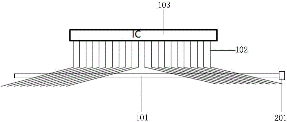
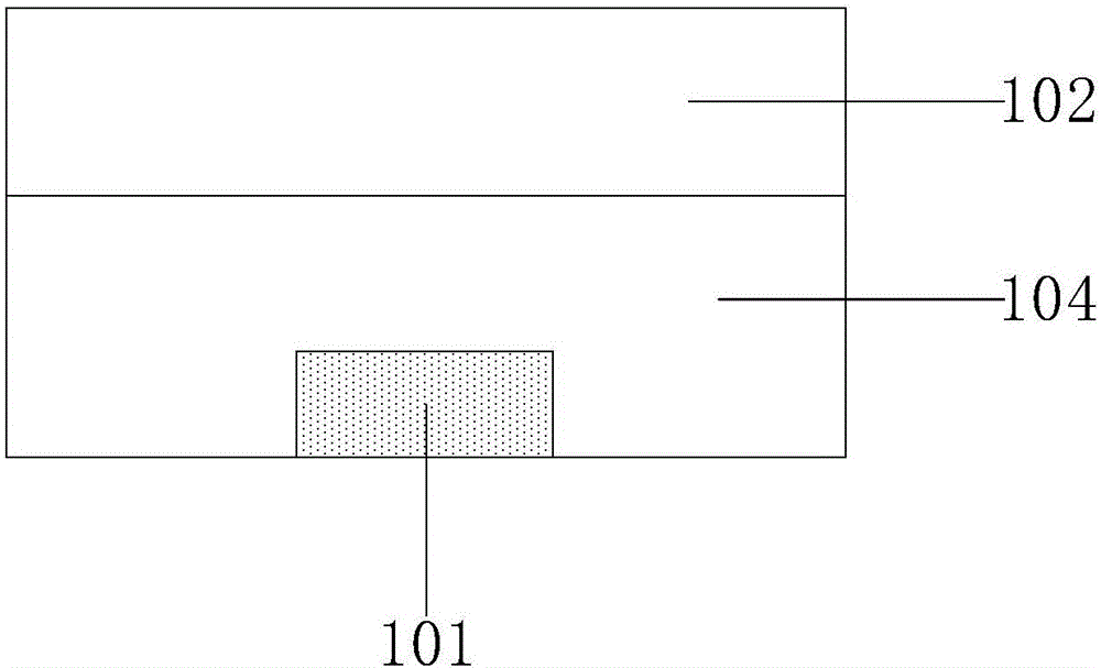
[0032] figure 1 It is a schematic structural diagram of a detection circuit provided in Embodiment 1 of the present invention, figure 2 for figure 1 Cross section of the detection circuit shown. Such as figure 1 and figure 2 As shown, the detection circuit includes a test line 101, a laser unit and a judgment unit, the test line 101 is connected to the judgment unit, and the test line 101 intersects with the projection of the signal line of the driver on the substrate substrate, so An insulating layer 104 is disposed between the test line 101 and the signal line. In this embodiment, the driver is a source driver 103, the signal line is a data line 102, and the test line 101 is routed in the same direction as the gate line.

[0033] In this embodiment, the laser unit is used to perform laser breakdown on the insulating layer 104, so that the test line 101 is connected to the data line 102, and the test line 101 is used to output the standby state of the data line 102. T...

Embodiment 2

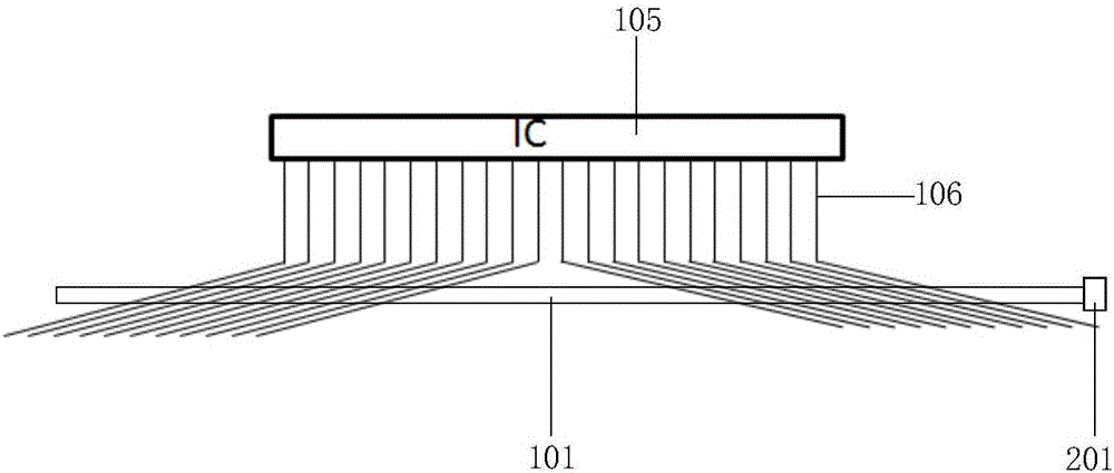
[0037] image 3 It is a schematic structural diagram of a detection circuit provided in Embodiment 2 of the present invention, Figure 4 for image 3 Cross section of the detection circuit shown. Such as image 3 and Figure 4 As shown, the detection circuit includes a test line 101, a laser unit and a judgment unit, the test line 101 is connected to the judgment unit, and the test line 101 intersects with the projection of the signal line of the driver on the substrate substrate, so An insulating layer 104 is disposed between the test line 101 and the signal line. In this embodiment, the driver is a gate driver 105, the signal line is a gate line 106, and the test line 101 is routed in the same direction as the data line.

[0038]In this embodiment, the laser unit is used to perform laser breakdown on the insulating layer 104, so that the test line 101 is connected to the gate line 106, and the test line 101 is used to output the waiting signal of the gate line 106. The...

Embodiment 3

[0042] This embodiment provides a driving circuit, including a driver and the detection circuit provided in Embodiment 1 or Embodiment 2. For specific content, please refer to the description in Embodiment 1 or Embodiment 2 above, which will not be repeated here.

[0043] In the drive circuit provided in this embodiment, the detection circuit includes a test line, a laser unit, and a judgment unit, the test line is connected to the judgment unit, and the test line and the signal line of the driver are connected to each other on the base substrate. The projections intersect, and an insulating layer is provided between the test line and the signal line; the laser unit is used to perform laser breakdown on the insulating layer, so that the test line is connected to the signal line to be tested; the The test line is used to output the signal to be tested of the signal line to be tested; the judging unit is used to judge whether the driving signal of the driver is abnormal according...


PUM


Abstract

The invention discloses a detection circuit, a working method of the detection circuit, and a driving circuit. The detection circuit comprises a test line, a laser unit and a judgment unit, wherein the laser unit is used for conducting laser breakdown on an insulating layer so as to enable the test line to be connected with a signal line to be detected, the test line is used for outputting a signal to be detected of the signal line to be detected, and the judgment unit is used for judging whether a driving signal of a driver is abnormal according to the signal to be detected. The test line is isolated from the signal line through the insulating layer, when an output signal of a certain signal line of the driver needs to be tested, laser breakdown is conducted on the insulating layer so as to make the test line connected with the signal line to be detected, and at the moment, the test line can output the signal to be detected of the signal line to be detected. According to the technical scheme, on the premise that normal work of the driver is not affected, the signal to be detected output by the test line is detected so that whether the output signal of the driver is abnormal can be judged, and then adverse analysis efficiency is improved and adverse analysis cost is reduced.

Description

technical field [0001] The invention relates to the field of display technology, in particular to a detection circuit, a working method thereof, and a driving circuit. Background technique [0002] During the failure analysis process of the liquid crystal display panel, many failure phenomena may be related to the inside of the display panel, and may also be related to the abnormal output of the driver. In the case of the above situation, the prior art needs to reinstall the driver to verify whether the signal output of the original driver is abnormal. Therefore, existing defect detection techniques are inefficient, risky, and costly. Contents of the invention [0003] In order to solve the above problems, the present invention provides a detection circuit, its working method, and a driving circuit, which at least partly solve the problems of low efficiency, high risk and high cost of the existing defective detection technology. [0004] To this end, the present inventio...

Claims


Application Information

Patent Timeline
Patent Type & Authority Applications(China)
IPC IPC(8): G09G3/00
CPCG09G3/006
Inventor 柯宇锷杨怀伟
Owner HEFEI BOE OPTOELECTRONICS TECH
Why Eureka
Try Eureka