
Current detection circuit-based comparative amplification type power supply for LED lamp band
A technology of current detection circuit and LED strip, applied in the field of electronics, can solve the problems of unstable output voltage and current of the power supply, poor load capacity, etc., and achieve the effect of reducing leakage current and loss current, ensuring stability and improving strength
Patent Information
- Authority / Receiving Office
- CN · China
- Patent Type
- Applications(China)
- Current Assignee / Owner
- Publication Date
- 2016-12-07
- Estimated Expiration
- Not applicable · inactive patent
Smart Images
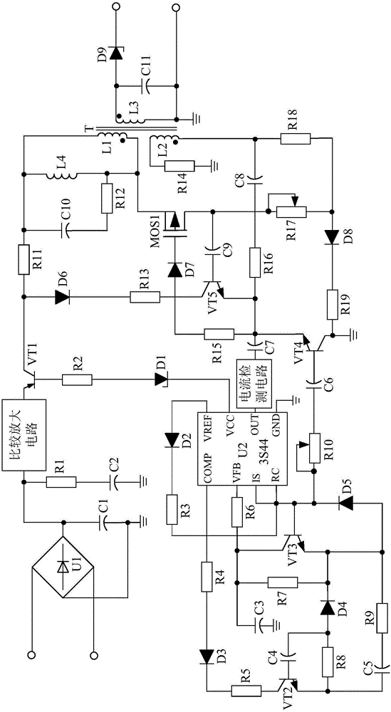
Figure 1 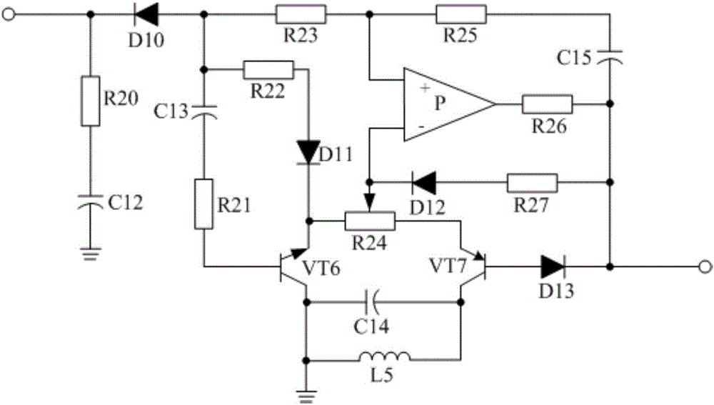
Figure 2 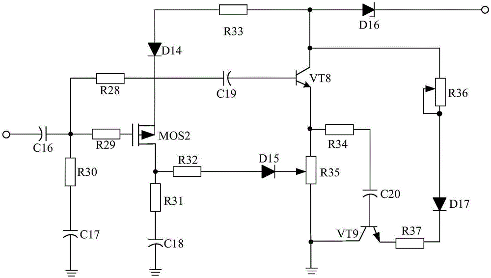
Figure 3
Abstract
Description
technical field
[0001] The invention relates to the field of electronics, specifically, a comparatively amplified power supply for LED light strips based on a current detection circuit. Background technique
[0002] At present, with the continuous improvement of people's living standards, the requirements for the beautification of the living environment are also getting higher and higher. In order to beautify their living environment, people use LED light strips with various light source colors to beautify the interior. However, the existing power supply for LED strips is susceptible to external electromagnetic wave interference, resulting in unstable output voltage and current, resulting in unstable brightness of the light-controlled LED lamp, which seriously affects the service life of the LED lamp; and the existing LED lamp There is also the problem of poor load capacity with the power supply.
[0003] Therefore, it is urgent to provide a power supply for LED light strip...
Examples
Embodiment
[0021] Such as figure 1As shown, the present invention is mainly composed of control chip U2, diode rectifier U1, transformer T, triode VT1, P pole is connected with the base of triode VT1 after resistor R2, and N pole is connected with the VCC pin of control chip U2. Voltage diode D1, the anode is connected to the positive output terminal of the diode rectifier U1, the negative pole is connected to the negative output terminal of the diode rectifier U1, and then the polarity capacitor C1 is grounded, and the positive pole is connected to the positive output terminal of the diode rectifier U1 after passing through the resistor R1 , The polarity capacitor C2 with the negative pole grounded, the P pole connected to the VREF pin of the control chip U2, the diode D2 connected to the N pole through the resistor R3 and the RC pin of the control chip U2, and the positive pole connected to the secondary inductance coil of the transformer T The polarity capacitor C11 connected to the s...