Ornithopter wing aerodynamic differential device and control method thereof

The technology of a differential device and a flapper is applied in the field of flapper design, which can solve the problems of low flight speed, inability to install ailerons, and low flight speed of flapper, and achieves improved aerodynamic force, low installation cost and economical efficiency. good effect

Active Publication Date: 2017-01-04
NORTHWESTERN POLYTECHNICAL UNIV
View PDF5 Cites 10 Cited by
  • Summary
  • Abstract
  • Description
  • Claims
  • Application Information

AI Technical Summary

Problems solved by technology

[0004] The problem with the current solution is that it is difficult for the wings of an orthopter to achieve the same stiffness in all directions at all positions, and compared with the fixed wing, the orthopter’s flight speed is low, and the rudder is difficult to generate a large enough steering moment
The wing of the orthopter produces a highly unsteady flow, and the aileron cannot be installed on the wing like a fixed-wing aircraft, but can only be installed on the tail, but the wingspan of the tail is limited, and the flapping wing is relatively At a low flight speed, the actual effect of the ailerons is also very limited
Moreover, this passive correction method itself will bring a lot of resistance and reduce the aerodynamic efficiency of the orthopter

Method used


Image

  • Ornithopter wing aerodynamic differential device and control method thereof
  • Ornithopter wing aerodynamic differential device and control method thereof
  • Ornithopter wing aerodynamic differential device and control method thereof

Examples


Embodiment Construction

[0028] Embodiments of the present invention are described in detail below, examples of which are shown in the drawings, wherein the same or similar reference numerals designate the same or similar elements or elements having the same or similar functions throughout. The embodiments described below by referring to the figures are exemplary and are intended to explain the present invention and should not be construed as limiting the present invention.

[0029] In describing the present invention, it should be understood that the terms "center", "longitudinal", "transverse", "length", "width", "thickness", "upper", "lower", "front", " Orientation indicated by rear, left, right, vertical, horizontal, top, bottom, inside, outside, clockwise, counterclockwise, etc. The positional relationship is based on the orientation or positional relationship shown in the drawings, which is only for the convenience of describing the present invention and simplifying the description, rather than ...


PUM


Abstract

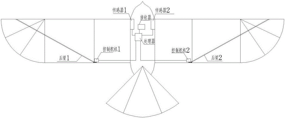
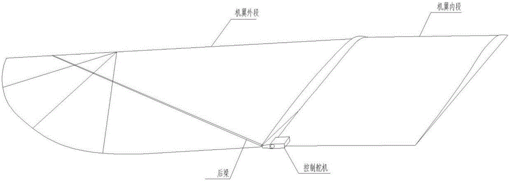
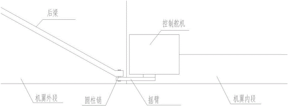
The invention provides an ornithopter wing aerodynamic differential device and a control method thereof to actively control aerodynamic forces of ornithopter wings. The ornithopter wing aerodynamic differential device comprises a processor, two sensors, two steering engines and two swing arms. The ornithopter wing aerodynamic differential device can actively control the aerodynamic forces of the wings by controlling pitching movement of opposite incoming flows generated in the flapping process of the wings and controlling the amplitude of the movement of the wing on the two sides, so that on one hand, aerodynamic force difference caused by stiffness difference between the wings in the manufacturing process can be eliminated, and on the other hand, the flying direction can be changed through the aerodynamic force difference between the two wings so as to substitute the role of a rudder and reduce the weight of an ornithopter.

Description

technical field [0001] The invention relates to the field of flapping aircraft design, in particular to an aerodynamic differential device of the flapping wing and a control method thereof. Background technique [0002] Compared with the traditional fixed-wing aircraft, the orthopter is fundamentally different in its flight mode. It relies on the flapping of the wings to generate thrust and lift as power to fly. It is required that the wings of the orthopter have a certain degree of flexibility in order to generate backward aerodynamic force when flapping. The stiffness of the wings will have a great impact on the aerodynamic force. When actually manufacturing an orthopter, it is often difficult The two wings are controlled to have the same stiffness, which causes different aerodynamic forces due to different stiffnesses when the wings flap, which causes the aircraft to generate yaw moments and roll moments, causing the aircraft to deviate from straight-line navigation and r...

Claims


Application Information

Patent Timeline
Patent Type & Authority Applications(China)
IPC IPC(8): B64C33/02
CPCB64C33/02B64U10/40
Inventor 刘辉崔卫民郭伟高杨凡洪林喻兴亮郭腾魏浩杨慧
Owner NORTHWESTERN POLYTECHNICAL UNIV
Why Eureka
Try Eureka