Check patentability & draft patents in minutes with Patsnap Eureka AI!

A phase change energy storage type oil and gas recovery equipment and recovery method

A technology of phase change energy storage and recovery equipment, which is applied in chemical instruments and methods, separation methods, recovery of liquid hydrocarbon mixtures, etc., can solve the problems of long recovery cost cycle, uneconomical, volume change, etc., and achieve one-time investment cost saving , saving manufacturing cost, and simplifying installation conditions

Active Publication Date: 2017-09-19
上海聚宸新能源科技有限公司
View PDF6 Cites 0 Cited by
  • Summary
  • Abstract
  • Description
  • Claims
  • Application Information

AI Technical Summary

Problems solved by technology

[0008] 1. After the tanker at the gas station is unloaded, some gas station operators need to manually check whether the tanker has been unloaded, and open the top cover of the tanker, causing the oil and gas in the tanker to be released into the atmosphere;
[0009] 2. The tank trucks that transport oil to the gas station may pull gasoline today, and then go to the oil depot to pull diesel tomorrow. However, the diesel stacks used by the oil depot to load the tank trucks are not equipped with oil vapor recovery equipment at all (for oil vapor recovery of diesel oil, There is no mandatory requirement in the country), which leads to the gasoline oil gas in the tanker running into the atmosphere in vain;
[0010] 3. The airtightness of the tank car is not tight, and the gas is easier than the liquid to cause a sharp change in volume due to temperature changes. The oil and gas in the tank car will increase the internal pressure of the tank car due to temperature changes. Many tank car covers, detection ports and other parts The airtightness is not tight, and the tank truck is running all over the street with the whole vehicle of oil and gas. When the next time it is loaded at the oil depot, the internal oil and gas may have been greatly reduced.
[0011] 4. Many tank cars have not been modified to load oil at the bottom, and the size of the upper oil loading port is different. The crane pipe of the oil depot cannot effectively seal the tank mouth of the tank car at all, so that the oil gas recovery equipment of the oil depot cannot collect high-concentration oil gas. Affect the yield of oil gas recovery equipment in oil depot
[0017] When unloading oil at a gas station, generally a tank car has a volume of 30-60 cubic meters, and the entire unloading process is generally completed in about one hour, that is, the amount of oil and gas produced is about 30-60Nm3 / h. In order to meet the requirements of oil and gas recovery treatment, equipment like the three oil and gas recovery needs 30 sets or magnified by about 30 times, which is obviously uneconomical. Gas station owners have installed oil and gas recovery treatment devices like tertiary oil and gas recovery or oil and gas recovery in oil depots for economic benefits. At present, no one has optimized the design of oil and gas recovery when unloading oil at gas stations.
[0018] For more than 90% of the gas stations in the country, there is only one tank truck unloading oil every day, or every two or three days, and each unloading takes about an hour. In this case, a set of oil and gas recovery treatment with a processing capacity of 50Nm3 / h Take equipment as an example, the market price is about 300,000 to 600,000 yuan, even if the oil of about 200 yuan can be recovered each time the oil is unloaded, the cycle of recovery cost is very long

Method used


Image

  • A phase change energy storage type oil and gas recovery equipment and recovery method
  • A phase change energy storage type oil and gas recovery equipment and recovery method
  • A phase change energy storage type oil and gas recovery equipment and recovery method

Examples


Embodiment 1

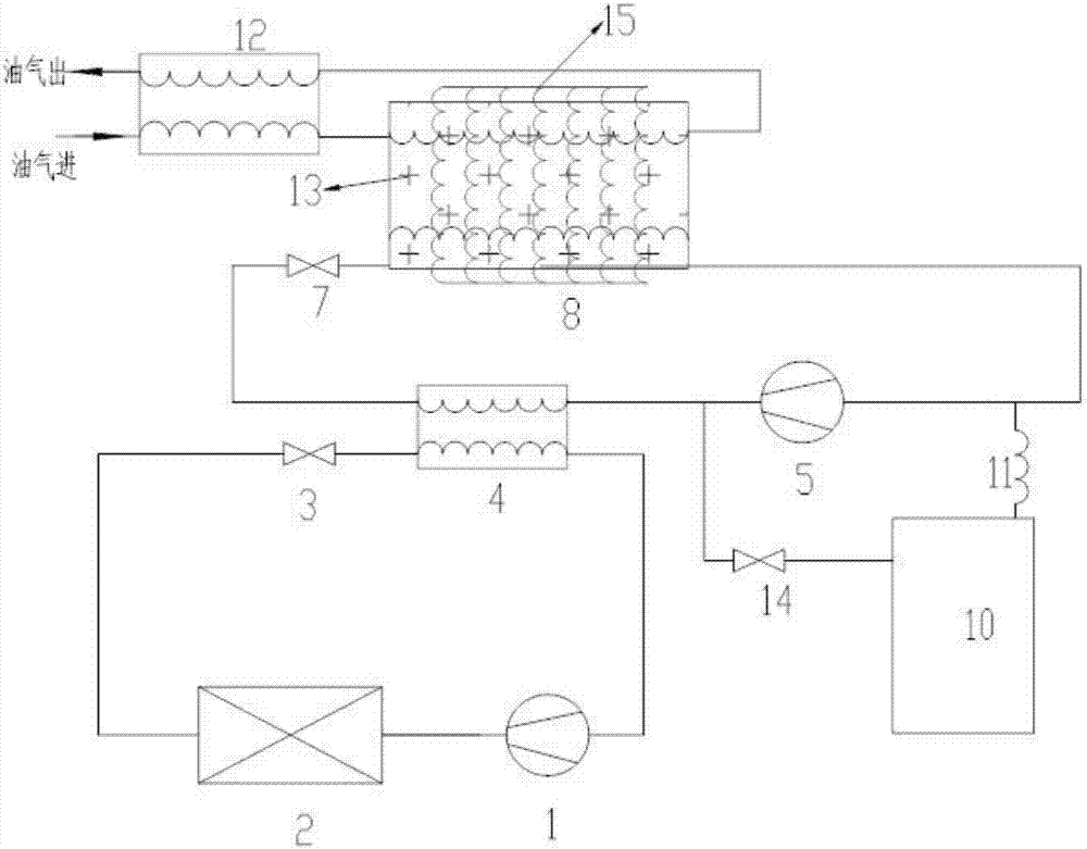
[0091] Such as image 3 As shown, the present invention discloses a phase change energy storage type oil and gas recovery equipment, including an oil and gas recovery device and a refrigeration storage device, wherein:

[0092] The oil and gas recovery device includes a first-stage oil-gas condenser 12 and a second-stage oil-gas condenser 8 connected in sequence, for making oil and gas input from the inlet on one side of the first-stage oil-gas condenser 12, and then condensing through the first-stage oil-gas After the precooling of the device 12 and the secondary oil-gas condenser 8, return to the first-stage oil-gas condenser 12 and output through the outlet on one side of the first-stage oil-gas condenser 12;

[0093]The refrigeration storage device includes a high-temperature compressor 1, an air condenser 2, a high-temperature throttling device 3, an evaporation condenser 4, and a low-temperature throttling device 7, and the high-temperature compressor 1, an air condenser...

Embodiment 2

[0103] like Figure 4 As shown, the present invention additionally discloses a phase change energy storage type oil and gas recovery equipment, including an oil and gas recovery device and a refrigeration and cold storage device, wherein:

[0104] The oil and gas recovery device includes a first-stage oil-gas condenser 12 and a second-stage oil-gas condenser 8 connected in sequence, for making oil and gas input from the inlet on one side of the first-stage oil-gas condenser 12, and then condensing through the first-stage oil-gas After the precooling of the device 12 and the secondary oil-gas condenser 8, return to the first-stage oil-gas condenser 12 and output through the outlet on one side of the first-stage oil-gas condenser 12;

[0105] The refrigeration storage device includes a high-temperature compressor 1, an air condenser 2, a high-temperature throttling device 3, an evaporation condenser 4, and a low-temperature throttling device 7, and the high-temperature compresso...

Embodiment 3

[0115] like Figure 5 As shown, the present invention additionally discloses a phase change energy storage type oil and gas recovery method, comprising the following steps:

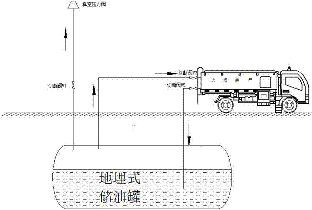
[0116] Step A1: The oil and gas generated when the tanker is unloaded is pre-cooled through the primary oil and gas condenser 12, so that the temperature is reduced to between -10° and +10°, and most of the water in the oil and gas is removed at the same time;

[0117] Step A2: The oil and gas pre-cooled by the first-stage oil-gas condenser 12 enters the second-stage oil-gas condenser 8, further reducing the temperature to -40° to -80°, and most of the hydrocarbons in the oil and gas are condensed and recovered. The remaining low-temperature gas returns to the first-stage oil-gas condenser 12, and performs heat exchange with the high-temperature oil-gas entering the first-stage oil-gas condenser 12, and then returns to the tank truck;

[0118] Step A3: The high-temperature and high-pressure refrigerant d...


PUM


Abstract

The invention discloses a device and method for phase change energy storage type oil gas recycling. The device comprises an oil gas recycling device and a refrigeration and cold accumulation device. The oil gas recycling device comprises a primary oil gas condenser and a secondary oil gas condenser which are connected in sequence. Oil gas is input through an inlet on one side of the primary oil gas condenser, is precooled through the primary oil gas condenser and the secondary oil gas condenser, returns into the primary oil gas condenser and is output through an outlet on one side of the primary oil gas condenser. The refrigeration and cold accumulation device comprises a high temperature grade compressor, an air condenser, a high temperature grade throttling device, an evaporative condenser and a low temperature grade throttling device. The high temperature grade compressor, the air condenser, the high temperature grade throttling device and the evaporative condenser are sequentially connected and form a first circulation loop, one end of the low temperature grade throttling device is connected with the evaporative condenser, and the other end of the low temperature grade throttling device is connected with the secondary oil gas condenser. According to the device, low temperature grade direct energy accumulation is adopted; compared with the prior art, the energy consumption is lower, and a refrigerating system is smaller.

Description

technical field [0001] The invention relates to the field of oil and gas recovery equipment, in particular to a phase change energy storage type oil and gas recovery equipment and a recovery method. Background technique [0002] At present, all gas stations have undergone compulsory oil and gas recovery transformation. The national mandatory oil and gas recovery includes primary oil and gas recovery and secondary oil and gas recovery. The country has not yet compelled three oil and gas recovery. [0003] Primary oil and gas recovery refers to the gas-liquid exchange between the oil tank truck and the underground oil tank (buried tank) of the gas station. [0004] When the tank truck unloads oil to the buried tank of the gas station (mainly for gasoline with high gas content), the "empty" buried tank is not actually empty, it is full of oil and gas, and the liquid oil in the tank truck depends on Gravity flows into the buried tank, and the oil and gas in the buried tank are ...

Claims


Application Information

Patent Timeline
Patent Type & Authority Patents(China)
IPC IPC(8): B67D7/54B67D7/80B01D53/00C10G5/06
CPCB01D53/002B67D7/54B67D7/80C10G5/06
Inventor 马中华
Owner 上海聚宸新能源科技有限公司
Features
  • R&D
  • Intellectual Property
  • Life Sciences
  • Materials
  • Tech Scout
  • Unparalleled Data Quality
  • Higher Quality Content
  • 60% Fewer Hallucinations
Learn More