Catalyst for cement kiln flue gas SCR denitration and denitration system

A cement kiln and catalyst technology, applied in the field of flue gas denitrification, can solve the problems of difficult to achieve ultra-low emission standards, easy wear and poisoning of catalysts, and high content of particulate matter at the inlet, and achieve long-term stable operation, good activity maintenance, and reduced particle concentration. Effect

Active Publication Date: 2019-08-16
JIANGSU CTIEC ENVIRONMENTAL PROTECTION RES INST
View PDF7 Cites 5 Cited by
  • Summary
  • Abstract
  • Description
  • Claims
  • Application Information

AI Technical Summary

Problems solved by technology

[0003] The cement industry achieves NO X Emissions below 100mg / m 3 It is imperative that the existing SNCR (Selective Non-Catalytic Reduction) denitrification technology is difficult to achieve ultra-low emission standards, and the replacement of the SCR (Selective Catalytic Reduction) denitrification technology widely used in coal-fired power plants is facing an entry point. Technical problems such as high particulate matter content and easy wear and poisoning of the catalyst lead to a sharp decline in its denitrification performance

Method used


Image

  • Catalyst for cement kiln flue gas SCR denitration and denitration system
  • Catalyst for cement kiln flue gas SCR denitration and denitration system

Examples


Embodiment 1

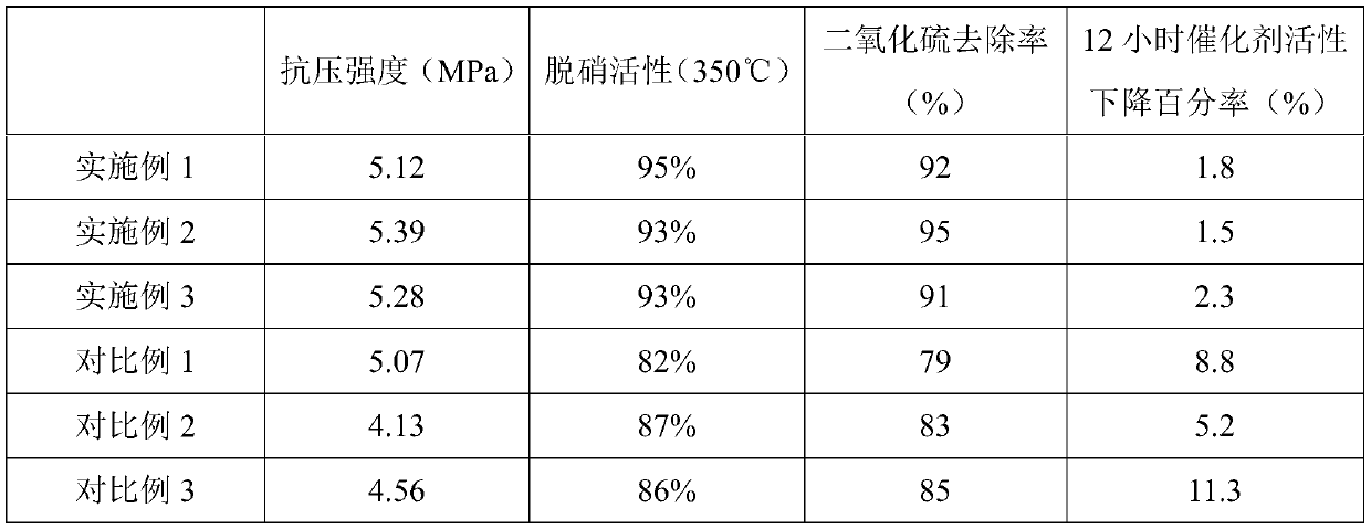
[0030] The catalyst for SCR denitrification of cement kiln flue gas in this embodiment includes the following components in parts by weight: 20 parts of silicon carbide, 5 parts of metal oxides, 3 parts of vanadium-titanium composite oxides, 1 part of binder and 0.5 part of lubricant agent.

[0031] Among them, the metal oxide is lanthanum oxide or cobalt oxide, the vanadium-titanium composite oxide is titanium dioxide / vanadium pentoxide composite oxide, and the binder is hydroxypropyl methylcellulose, starch, carboxymethylcellulose or polyethylene One or more alcohols, and the lubricant is glycerin or tung oil.

[0032] The preparation method of this embodiment comprises the steps:

[0033] S1. Carrier preparation: add silicon carbide, metal oxides, part of the binder and part of the lubricant into the ball mill at the same time for ball milling for 2-4 hours, and grind until the particle size is 200-400 mesh to obtain the catalyst carrier;

[0034] S2. Add the catalyst car...

Embodiment 2

[0041] The cement kiln flue gas SCR denitrification catalyst of this embodiment is roughly the same as that of Embodiment 1, the difference lies in the content of each component, specifically as follows: 30 parts of silicon carbide, 10 parts of metal oxide, 5 parts of vanadium-titanium composite oxide, 2 1 part adhesive and 1 part lubricant.

[0042] The preparation method of this example is exactly the same as that of Example 1, and will not be repeated here.

Embodiment 3

[0044] The cement kiln flue gas SCR denitrification catalyst of this embodiment is roughly the same as that of Embodiment 1, the difference lies in the content of each component, specifically as follows: 50 parts of silicon carbide, 15 parts of metal oxide, 8 parts of vanadium-titanium composite oxide, 2.5 1 part adhesive and 2 parts lubricant.

[0045] The preparation method of this example is exactly the same as that of Example 1, and will not be repeated here.


PUM

PropertyMeasurementUnit
thicknessaaaaaaaaaa

Abstract

The invention discloses a catalyst for SCR denitration of cement kiln flue gas, a preparation method of the catalyst and a denitration system. The catalyst comprises 20-50 parts of silicon carbide, 5-15 parts of metal oxide, 3-8 parts of a vanadium-titanium composite oxide, 1-2.5 parts of an adhesive and 0.5-2 parts of a lubricant. The metal oxide is lanthanum oxide or cobalt oxide. The vanadium-titanium composite oxide is a titanium dioxide/vanadium pentoxide composite oxide. The denitration system comprises a preheater system, an intercepting net system, a ceramic filter pipe integrated system, an SCR denitration system and a waste heat power generation system, which are arranged in the flowing direction of flue gas. According to the invention, the catalyst carrier is prepared from silicon carbide and metal oxide, and the self-made composite oxide is used as the catalyst, so that the catalyst with good low-temperature activity, high sulfur resistance and good activity retention is prepared. The denitration system can greatly reduce one-time investment and operation cost of downstream desulfurization and dust removal equipment.

Description

technical field [0001] The invention relates to a catalyst, in particular to a catalyst and a denitrification system for SCR denitrification of flue gas from a cement kiln, and belongs to the technical field of flue gas denitrification. Background technique [0002] There are more than 3,000 cement enterprises in my country, and about 1,800 new-type dry-process clinker production lines, covering 31 provinces and cities across the country. The annual emission of nitrogen oxides in the cement production process is about 2 million tons, accounting for about 2 million tons of nitrogen oxide industrial emissions in the country. It is the third largest source of nitrogen oxide emissions after electricity and vehicle exhaust. [0003] The cement industry achieves NO X Emissions below 100mg / m 3 It is imperative that the existing SNCR (Selective Non-Catalytic Reduction) denitrification technology is difficult to achieve ultra-low emission standards, and the replacement of the SCR (S...

Claims


Application Information

Patent Timeline
Patent Type & Authority Applications(China)
IPC IPC(8): B01J27/224B01D53/86B01D53/60B01D53/79B01D53/83B01D53/75
CPCB01D53/60B01D53/75B01D53/79B01D53/83B01D53/8628B01D53/8637B01D2251/2062B01D2251/404B01D2251/604B01D2258/0233B01D2258/0283B01J23/002B01J27/224B01J2523/00B01J2523/3706B01J2523/47B01J2523/55B01J2523/845
Inventor 张志刚王东歌
Owner JIANGSU CTIEC ENVIRONMENTAL PROTECTION RES INST
Why Eureka
Try Eureka