
Robot relocation method and device

A robot and relocation technology, applied in the field of robotics, can solve the problems of robot task termination, positioning errors, and increased mapping costs, and achieve the effect of avoiding increased mapping costs.

Active Publication Date: 2017-01-11
SHENZHEN WEIFU ROBOT TECH CO LTD
View PDF5 Cites 37 Cited by
  • Summary
  • Abstract
  • Description
  • Claims
  • Application Information

AI Technical Summary

Problems solved by technology

[0004] In view of this, the purpose of the embodiments of the present invention is to provide a robot relocation method and device to solve the problem that in the prior art, when the laser-based SLAM has a positioning error, it needs to re-build the map, which on the one hand leads to the cost of map-building Added, on the other hand, the problem that caused the task that the robot was performing to terminate

Method used


Image

  • Robot relocation method and device
  • Robot relocation method and device
  • Robot relocation method and device

Examples


Embodiment 1

[0062] The embodiment of the present invention provides a method for robot relocation. When the position of the robot located in the map constructed by SLAM is wrong, the method provided by the embodiment of the present invention is used to relocate the robot without rebuilding the map, avoiding The situation where the cost of mapping increases due to re-mapping and the robot terminates the task it is performing.

[0063] When the robot is performing a certain task or moving, the laser ranging system on the robot will continuously emit laser light, and the emitted laser light will be reflected back when it encounters an obstacle, and the reflected signal can be used to determine whether there is an obstacle. In this way, the obstacle avoidance and path planning of the robot can be realized.

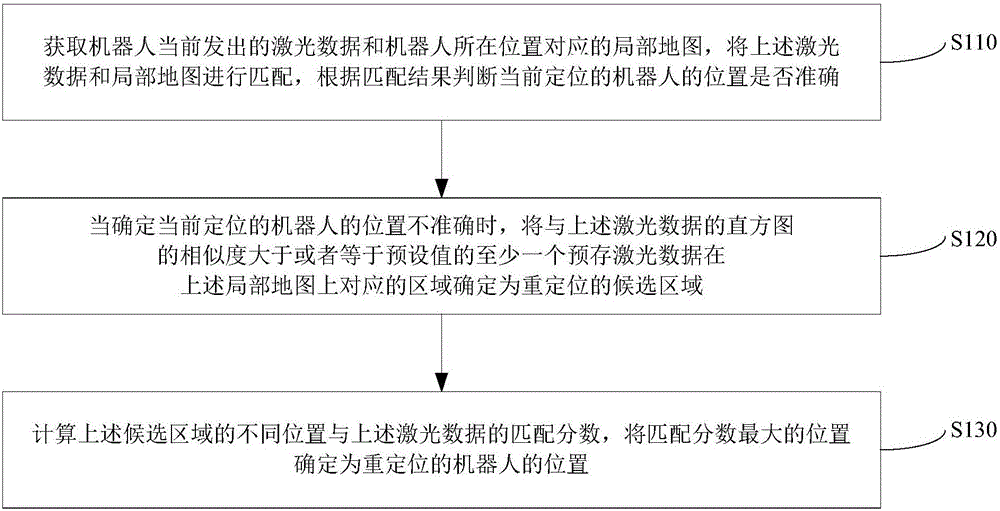
[0064] Such as figure 1 As shown, the robot relocation method provided by the embodiment of the present invention specifically includes steps S110-S130.

[0065] S110, acquiring laser ...

Embodiment 2

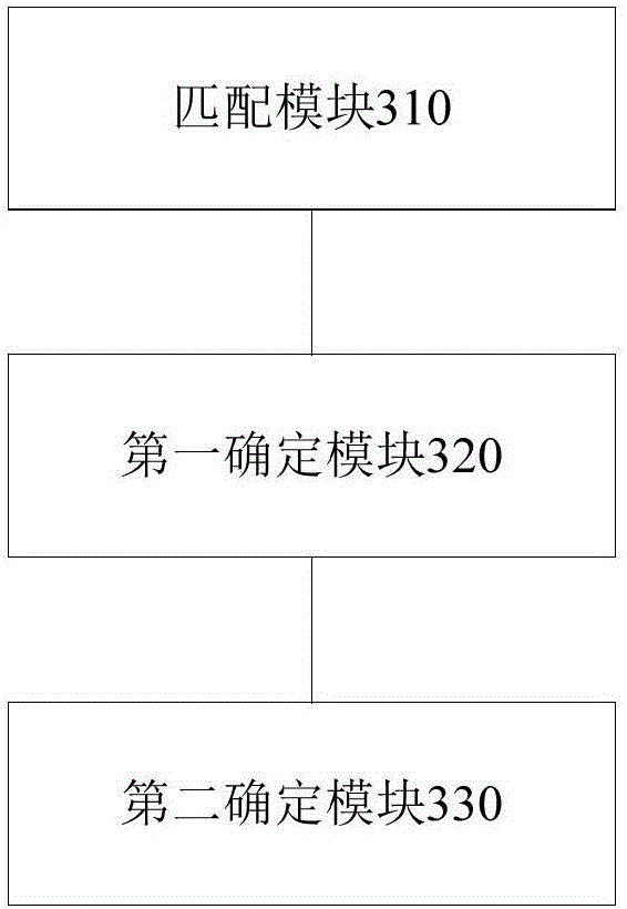
[0107] An embodiment of the present invention provides a robot relocation device, such as image 3As shown, the device provided by the embodiment of the present invention includes a matching module 310, a first determination module 320, and a second determination module 330;

[0108] The above-mentioned matching module 310 is used to obtain the laser data currently emitted by the robot and the local map corresponding to the location of the robot, match the above-mentioned laser data and the local map, and judge whether the position of the currently positioned robot is correct according to the matching result;

[0109] The above-mentioned first determination module 320 is configured to, when it is determined that the position of the currently positioned robot is inaccurate, at least one pre-stored laser data whose similarity with the histogram of laser data is greater than or equal to a preset value corresponds to the above-mentioned local map. The region is determined as a can...


PUM


Abstract

The invention provides a robot relocation method and device. The method comprises the steps of acquiring laser data transmitted by a robot currently and a local map corresponding to the position of the robot, matching the laser data with the local map, and judging whether the position of the robot currently located is correct according to a matching result; determining the area, corresponding to at least one prestored laser datum of which similarity to a histogram of the laser data is larger than or equal to a preset value, in the local map as a relocation candidate area if not; calculating the matching scores of different positions of the candidate area and the laser data, and determining the position with the largest matching score as the position of the relocated robot. According to the method, the robot is relocated when it is determined that the position of the robot currently located is incorrect, remapping is not needed, and increase of mapping cost and stop of a task which is being executed by the robot caused by remapping are avoided.

Description

technical field [0001] The present invention relates to the technical field of robots, in particular to a method and device for relocating a robot. Background technique [0002] When the robot is moving, it needs a two-dimensional laser ranging sensor to continuously emit laser light to measure the distance between the robot and the obstacle, so that the robot can avoid obstacles. It is widely used in the navigation of mobile robots, and based on Simultaneous Localization and Mapping (SLAM) of the laser sensor can position itself according to the position estimation and map during the movement of the robot, and build an incremental map on the basis of its own positioning to realize the landlord positioning of the robot and navigation. [0003] However, laser-based SLAM often has positioning errors due to human movement or the system itself. When such problems occur, most of the existing technologies start to build maps again. However, rebuilding Figure 1 On the one hand, i...

Claims


Application Information

Patent Timeline
IPC IPC(8): G01C21/00G01C21/20G01S17/02G01S17/06G01S17/93
CPCG01C21/005G01C21/20G01S17/04G01S17/06G01S17/93
Inventor 郑慧
Owner SHENZHEN WEIFU ROBOT TECH CO LTD
Learn More