Adjustable circular optical device positioning fixture

A technology for positioning fixtures and optical devices, applied in the field of optics, can solve the problems of high cost, waste of time and space, etc., and achieve the effect of satisfactory processing quality

Inactive Publication Date: 2017-01-25
YIXING JINGKE OPTICAL INSTR
View PDF6 Cites 3 Cited by
  • Summary
  • Abstract
  • Description
  • Claims
  • Application Information

AI Technical Summary

Problems solved by technology

The existing positioning fixtures for circular optical components can only be used to position optical components with a fixed aperture, and the corresponding positioning fixtures must be replaced when grindi

Method used


Image

  • Adjustable circular optical device positioning fixture

Examples


Embodiment Construction

[0013] The present invention will be further described below in conjunction with the accompanying drawings and embodiments.

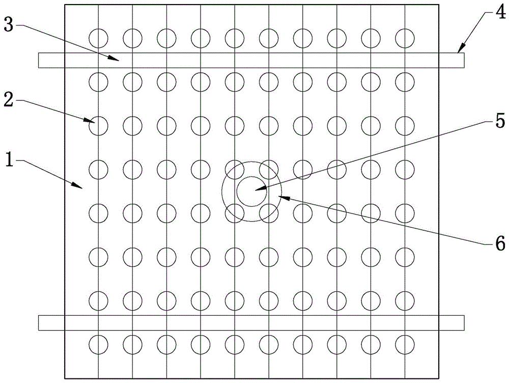
[0014] Such as figure 1 Shown: an adjustable circular optical device positioning fixture, including an adjustable clamp block 1, on one side or both sides of the adjustable clamp block 1 is provided with evenly distributed semicircular holes, and a plurality of adjustable clamp blocks 1 are assembled Together, the corresponding semicircular holes on the adjacent adjustable clamp blocks 1 are combined to form the workpiece hole 2, and the positioning fixture formed by a plurality of adjustable clamp blocks 1 is provided with a mandrel hole 3, and the mandrel 4 is inserted into the multiple adjustable clamp The block 1 is fixed to form a positioning fixture, and the tightness of the mandrel 4 is adjusted so that the workpiece hole 2 can accommodate workpieces with different diameters. In the above-mentioned positioning fixture, the mandrel hole 3 is loca...


PUM


Abstract

The invention discloses an adjustable circular optical device positioning fixture. The adjustable circular optical device positioning fixture comprises adjustable clamping blocks (1), wherein a single side or dual sides of the adjustable clamping block (1) are provided with semicircular holes which are distributed uniformly; the plurality of adjustable clamping blocks (1) are assembled together, so that corresponding semicircular holes in adjacent adjustable clamping blocks (1) are combined into workpiece holes (2); the positioning fixture constructed by the plurality of adjustable clamping blocks (1) is provided with a mandrel hole (3); a mandrel (4) is inserted into the mandrel hole to fix the plurality of adjustable clamping blocks (1) in order to construct the positioning fixture; the workpiece holes (2) can accommodate workpieces of different apertures by adjusting the tightness of the mandrel (4). In the positioning fixture, the workpiece holes (2) can accommodate the workpieces of different apertures by adjusting the tightness of the mandrel (4), workpieces to be machined are prevented from moving and deviating in a machining process, and ports of protruding ends of the workpieces can be ground or polished stably, so that the requirement on machining quality of the workpieces to be machined is met.

Description

technical field [0001] The invention relates to the field of optical technology, in particular to an adjustable circular optical device positioning fixture capable of accommodating workpieces with different apertures. Background technique [0002] A fixture is a device that precisely supports, positions and clamps one or more workpieces to facilitate the processing, grinding, and cutting of the workpiece, or as a device for assembly, inspection, etc. The fixture can be used in a large number of The production is in the middle, reducing the waste of working hours, improving production efficiency, maintaining product quality and reducing defective rate. Although the fixture itself does not have the function of grinding and cutting, it can accurately locate the workpiece at a certain position, and firmly clamp it to this position to withstand the force applied by the tool during processing. A device used to fix the processing object in the production process so that it occupie...

Claims


Application Information

Patent Timeline
IPC IPC(8): B25B11/00B24B41/06
CPCB25B11/00B24B41/066
Inventor 欧仕明石矿潘晓波欧国春殷卫强
Owner YIXING JINGKE OPTICAL INSTR
Why Eureka
Try Eureka