

Work fixture for double-side grinding and polishing machine
A technology of double-sided grinding and fixtures, which is applied in the optical field, can solve the problems of time-consuming and laborious production costs, and achieve the effects of high production efficiency, satisfactory processing quality, and not easy to break
- Summary
- Abstract
- Description
- Claims
- Application Information
AI Technical Summary
Problems solved by technology
Method used
Image

Examples
Embodiment Construction
[0015] The present invention will be further described below in conjunction with the accompanying drawings and embodiments.
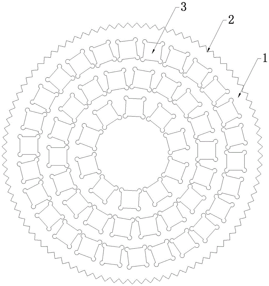
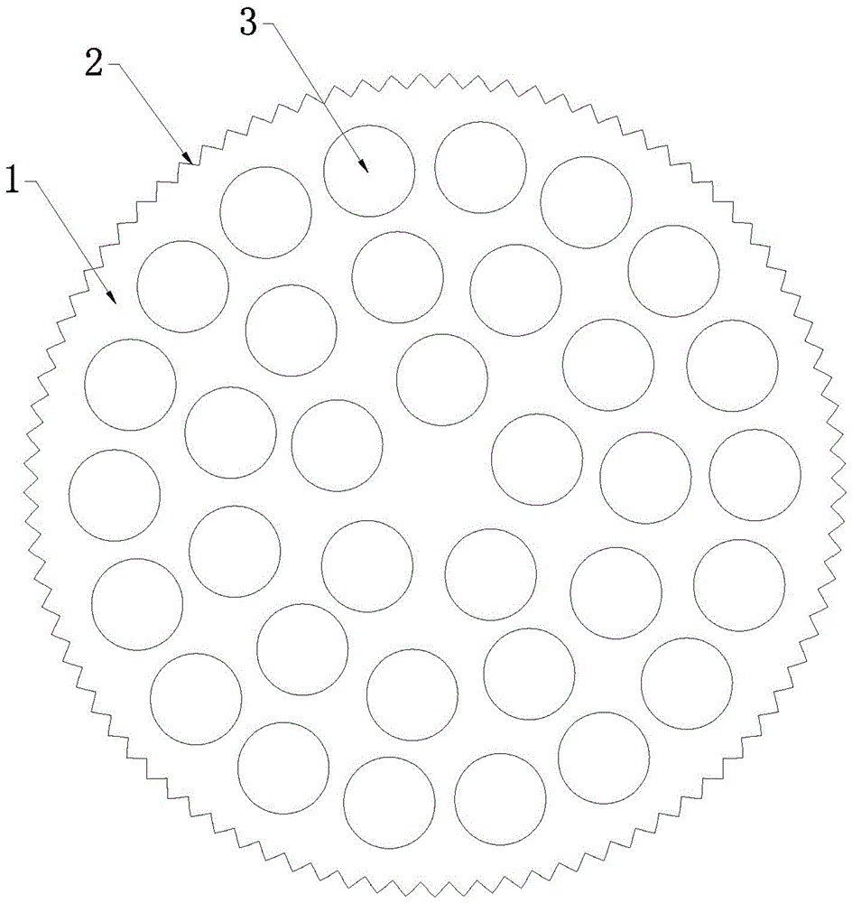
[0016] Such as Figure 1-2 Shown: a fixture for double-sided grinding and polishing machines, including a fixture body 1, the fixture body 1 is disc-shaped and the outer edge of the fixture body 1 is provided with evenly distributed gear slots 2, the gear slots 2. It can mesh with the sun gear and the inner ring gear of the double-sided grinding and polishing machine at the same time. There is a hollow workpiece groove 3 on the fixture body 1, so that the upper and lower surfaces of the workpiece to be processed in the workpiece groove 3 can be ground and polished And the workpiece to be processed can rotate by itself. In the above fixture, the thickness of the fixture body 1 is greater than the thickness of the workpiece to be processed; the inner contour of the workpiece groove 3 matches the outer contour of the workpiece to be processed; specificall...
PUM
 Abstract
Description
Claims
Application Information